


- Valve elements with 4 ways and 2 positions.
- Control spools directly operated by solenoids with removable coils.
- In the de-energized condition, the control spool is held in the central position by return spring.
- Wet pin tubes for DC coils, with push rod for mechanical override; burnish surface treatment.
- Manual override (push-button or screw type) available as option.
- Additional solenoid cartridge 2/2, NO or NC, single locking or dual locking on port A.
- Size 4
- Series 00
- Maximum operating pressure 310 bar (4500 psi)
- Maximum flow 25 l/min (6.6 gpm)
- Port connections G 3/8 SAE6 - M16x1.5
B8_5A... (EDB-A-VEI)
1)
For connectors ordering code see data sheet RE 18325-90.
2)
VEI solenoid cartridge must be ordered separately.
The secondary valves have a maximum flow capacity of 6 l/min. (1.6 gpm).
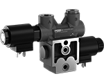
The sandwich plate design directional valve elements B8_5A... are very compact direct operated solenoid valves which control the start, the direction and the leak free stop of the oil flow. These elements basically consist of a stackable housing (1) with a control spool (2), one solenoid (5), a spring holder plug (7); two return springs (4); a solenoid screw-in cartridge VEI (8) with its coil (9). When energized, the force of the solenoid (5) pushes the control spool (2) from its rest position “0” to the end position “b”. If there is a solenoid cartridge VEI (8) type C, A, O, the oil flow goes directly to the port A; if there is a solenoid cartridge VEI (8) type D (Dual locking), it is necessary to energize the solenoid cartridge as well in order to allow the oil flow to the port A.
Once the solenoid (5) is de-energized, the return spring (4) pushes the spool thrust washer (3) back against the housing and the spool (2) returns in its rest position. The leak free holding at port A is provided by energizing (or de-energizing, if the VEI is NC type) the solenoid cartridge. By energizing open the VEI (8) (“C“ and “A“ versions), the A port is open to tank and downstream flow is possible. The coils are fastened to the respective solenoids (5) and VEI (8) by the ring nuts (6) and (10).
![]() For applications with different specifications consult us
For applications with different specifications consult us
Code
Voltage [V]
Connector type
Coil description
Marking
Coil Mat no.
OB 01
12 DC
EN 175301-803(Ex. DIN 43650)
D3601 12DC
12V DC
R901393412
OB 03
12 DC
AMP JUNIOR
D3603 12DC
12V DC
R901435507
OB 04
12 DC
AMP JUNIOR Horizontal
D3604 12DC
12V DC
R901395031
OB 07
12 DC
DEUTSCH DT 04-2P
D3607 12DC
12V DC
R901394397
OC 01
24 DC
EN 175301-803 (Ex. DIN 43650)
D3601 24DC
24V DC
R901393577
OC 03
24 DC
AMP JUNIOR
D3603 24DC
24V DC
R901435494
OC 04
24 DC
AMP JUNIOR Horizontal
D3604 24DC
24V DC
R901395035
OC 07
24 DC
DEUTSCH DT 04-2P
D3607 24DC
24V DC
R901394399
OD 01
48 DC
EN 175301-803(Ex. DIN 43650)
D3601 48DC
48V DC
R901394117
OU 01
96 DC
EN 175301-803(Ex. DIN 43650)
D3601 96DC
96V DC
R901394229
AH 01
205 DC
EN 175301-803(Ex. DIN 43650)
D3601 205DC
205V DC
R901394231
General:
Valve element with solenoid:
- kg (lbs) 1.8 (3.96)
Fluid Temperature:
- () -30....+90 (-22....+194) (NBR seals)
Hydraulic:
Maximum pressure at P, and A ports:
- 310 bar (4500 psi)
Maximum pressure at T:
- 250 bar (3625 psi)
Maximum inlet flow:
- 25 l/min (6.6 gpm)
Hydraulic fluidGeneral properties: it must have physical lubricating and
chemical properties suitable for use in hydraulic systems such as, for
example:
- Mineral oil based hydraulic fluids HL (DIN 51524 part 1). For use of environmentally acceptable fluids (vegetable or polyglycol base) please consult us.
Fluid Temperature:
- -30....+100°C (-22....+212°F) (NBR seals)
Permissible degree of fluid contamination:
- ISO 4572: βₓ≥75 X=12...15 NAS 1638: class 9
Viscosity range:
- 5....420 mm²/s
Electrical:
Voltage type:
- DC (AC only with RAC connection)
Voltage tolerance (nominal voltage):
- -10 +10%
Duty:
- Continuous, with ambient temperature < 50°C (122°F)
Coil wire temperature not to be exceeded:
- 150°C (302°F)
Insulation class:
- H
Compliance with:
- Low Voltage Directive LVD 73/23/EC (2006/95/EC), 2004/108/EC
Coil weight with connection EN 175301-803:
- kg (lbs) 0.18 (0.40)
Voltage:
- V 12
- V 24
- V 48
- V 96
- V 205
Voltage type:
- DC
- DC
- DC
- DC
- DC
Power consumption:
- 20 W
- 20 W
- 20 W
- 20 W
- 20 W
Current (nominal at 20 °C (68 °F)):
- 1.62 A
- 0.84 A
- 0.45 A
- 0.21 A
- 0.01 A
Resistance (nominal at 20 °C (68 °F)):
- 7.4 Ω
- 28.4 Ω
- 106.4 Ω
- 451 Ω
- 2062 Ω
Spool Variant
Curve no.
B>T
P>A
X301
1
2
Measured with hydraulic fluid ISO-VG32 at 45° ±5 °C (113° ±9 °F); ambient temperature 20 °C (68 °F).
Spool Variant
Curve no.
X401
1
The performance curves are measured with flow going across and coming back, like P>A and B>T, with symmetrical flow areas.
In case of special circuit connections, the performance limits can change.
Secondary valve setting
Curve no.
50-210 bar (700-2950 psi)
0
100-310 bar (1400-4500 psi)
1
25-50 bar (350-700 psi)
2
1
Solenoid tube Ø 16mm (0.63inch).
2
Screw-in solenoid cartridge VEI hex 24mm (0.94inch).
3
Ring nut for cartridge coil locking (Ch.24); torque 2-3Nm (1.5-2.2 ft-lb).
4
Ring nut for tube coil locking (OD 26.5); torque 3-4Nm (2.2-3 ft-lb).
5
Identical label.
6
Clearance needed for connector removal.
7
Optional push-button manual override, EP type, for spool opening: it is pressure stuck to the ring nut for tube coil locking.Mat no. R930059524.
8
Optional screw type manual override, EF type, for spool opening: it is screwed (torque 5-6Nm (3.7-4.4 ft-lb)) to the tube as replacement of the coil ring nut. Mat no. R930059561.
9
Optional manual override for VEI cartridge: it can be push/pull or screw type. Please refer to the VEI catalogue for details.
10
Flange specifications for coupling to ED intermediate elements.
11
For tie rod and tightening torque information see data sheet RE 18301-90.
12
O-Ring for T and P line on ED flange.
13
Space needed for secondary valve in configuration 1.
14
A and B ports