Compact Directional Valves - Non-compensated and Post-compensated - Inlet elements ED Series

TE13

Description

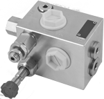
The inlet elementsTE-13-__ are employed to connect the external P, T lines to the P, T channels inside the ED elements of the Directional Valve Assembly and to connect the LS line for inlet flow control. An LS controlled 3-way compensator provides pressure compensated flow to the ED elements of the Directional Valve Assembly, any excess flow si bypassed to tank at LS pressure plus compensator spring bias. When the ED elements are in neutral position, the compensator bypasses the entire flow to tank at a bypass pressure equal to the compensator spring bias. In case the LS pressure reaches the relief pressure setting, the compensator unloads to tank the entire flow at relief pressure plus compensator spring bias The TE-13 can be equipped with a NO or NC Solenoid Unloading VEI Cartridge, which can be employed to unloads to tank the LS signal and bypasses the entire flow to tank at a bypass pressure equal to the compensator spring bias. The TE-13 is provided with non compensated bleed down orifice. The TE-13-…. is made of zinc plated cast iron. The coil S8-356 must be ordered separately (refer to RE18325-90).

General
TE13:
  • 3.6 kg (7.9 lbs)
Fluid Temperature:
  • –20….+50 (-4....+122) (NBR seals)
Hydraulic
Maximum pressure:
  • 310 bar (4500 psi)
Maximum inlet flow:
  • 33 l/min (8.7 gpm) TE-13-_ _-3 version
Maximum inlet flow:
  • 50 l/min (13.2 gpm) TE-13-_ _-5 version
Maximum inlet flow:
  • 80 l/min (21.1 gpm) TE-13-_ _-8 version
Maximum inlet flow:
  • 120 l/min (31.7 gpm) TE-13-_ _-0 version
Rated flow at P1:
  • Variable 1) l/min (gpm)
Hydraulic fluid General properties: it must have physical lubricating and chemical properties suitable for use in hydraulic systems such as, for example:
  • Mineral oil based hydraulic fluids HL (DIN 51524 part 1). Mineral oil based hydraulic fluids HLP (DIN 51524 part 2). For use of environmentally acceptable fluids (vegetable or polyglycol base) please consult us.
Fluid Temperature:
  • -20....+80 °C (-4....+176 °F) (NBR)
Permissible degree of fluid contamination:
  • ISO 4572: βx≥75 X=10...12 ISO 4406: class 19/17/14 NAS 1638: class 8
Viscosity range:
  • Note: 1) The maximum regulated flow on P1 line is related both to the pressure drop of the ED valve assembled on the group and their spools size.
  • Note: For applications with different specifications consult us
  • 5....420 mm2/s
RE18300-13-order
RE18300-13-sym
Pressure drop trough compensator
Model
Curve no.
TE-13-_ _-3_- 14 Version
1
TE-13-_ _-5_- 14 Version
2
TE-13-_ _-8_- 14 Version
3
TE-13-_ _-0_- 14 Version
4


Model
Curve no.
TE-13-_ _-3_- 18/R8 Version
5
TE-13-_ _-5_- 18/R8 Version
6
TE-13-_ _-8_- 18/R8 Version
7
TE-13-_ _-0_- 18/R8 Version
8
TE-13-_ _-0_- R8 lowest adjustable setting
9

Flow rate compensation (P1)


Fixed orefice
Curve no.
Ø0.5mm
1
Ø0.4mm
2
Ø0.3mm
3
RE18300-07-dim
1
Flange specifications for coupling to the ED Directional Valve Elements.
2
For tie rod and tightening torque information see data sheet RE 18301-90.
3
Hydraulic ports P and T G1/2, inlet elements TE-13-03-...
4
Hydraulic ports P and T G3/4, inlet elements TE-13-04-...
5
Test point LS port G1/4, inlet elements TE-13-03-..and TE-13-04.
6
Hydraulic ports P and T SAE10, inlet element TE-13-57-...
7
Test point LS port SAE6, inlet element TE-13-57-...
8
Pressure relief cartridge VMD1020, with screw type adjuster.
9
Unloading valve CA-08A-2N cavity plug TE-13-..-..-..-.P-.
10
Solenoid Unloading cartridge VEI-8A-2T-06... type.
11
VEI Coil S8-356 ordered separately.
12
Both adjustable cracking pressure version (R8) and locking option (BR).
13
Maximum torque of the nut 5-6 Nm (R8 and BR).
14
Maximum torque of the locking screw (BR) 9-10 Nm.