


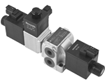
- 4/3 direct operated solenoid controlled directional valve with an electromagnetic mechanical detent on the control spool, specifically designed for steering mode selection.
- Zero power consumption during two wheel steering mode.
- Control spool with positive overlapping to reduce leakage and switching shocks.
- Stand-alone zinc plated valve housing with threaded ports and fixing holes for direct line mounting.
- Wet pin solenoid tubes for DC coils, with inherent push rod for mechanical override on the control spool; zinc plated.
- Standard coil connections available in DIN and DEUTSCH (additional connections on request).
- Size 6
- Series 00
- Maximum operating pressure 210 bar (3046 psi)
- Maximum peak pressure 230 bar (3336 psi)
- Maximum flow 50 l/min (13.2 gpm)
- Ports G 3/8 - G1/2 - SAE 8
SMV2
1)
Choosing the nominal voltage of the coils “a” and “b” the nominal voltage of the coil “c” is automatically defined. For customization contact factory.
2)
For “a” and “b” coils 13VDC coil “c”= 14VDC (see data sheet RE18325-90).
3)
For “a” and “b” coils 27VDC coil “c”= 26VDC ( see data sheet RE18325-90)
The SMV2.0 directional control valves with electromagnetically actuated mechanical detent are used for selecting between three steering modes.
In the de-energized condition, the control spool (3) is held in the center position by return springs (4); the spring (8) pushes the detent pin(1) against the bushing (7). In this condition the valve is in the front steering configuration (2WS) as all of the coils are de-energized.
In order to switch the steering mode (see pictures below), it is necessary to first actuate the mechanical detent by energizing the coil “c” in order to allow the control spool to move.
Then, by energizing one of the coils “a” or “b”, the control spool switches from the center position (2WS) to a different steering mode, 4WS-A or 4WS-B.
When a 4WS mode is selected, the control spool coil, “a” or “b”, must continue to be energized during machine operation; it is also necessary to de-energize the coil “c” to lock the mechanical detent into position. The mechanical interference between the bushing (7) and the detent pin(1) locks the control spool and prevents unwanted movements generated from external agents. (i.e. short circuit on the coils “a” or “b”).
The return springs guarantee the return to the center position by pushing on the washer (5) that is against the control spool.
The following shows the logical sequence of operation that guarantees the valve operates correctly.
Steering mode selection from 2WS to 4WS-A (locked)
Time
Coil A
Coil B
Coil C
Steering mode
note:
Initial status 2WS
OFF
OFF
OFF
2WS
Current steering mode selection
t=0
OFF
OFF
ON
2WS
Coil C is energized to disengage mechanical detent.
t=50ms
ON
OFF
ON
transient 2WS -> 4WS-A
After 50ms, coil A can be energized (the reaction time of coil C).
t=150ms
ON
OFF
OFF
4WS-A (unlocked)
After 100ms, coil C can be de-energized (the reaction time of coil A).
t=200ms
ON
OFF
OFF
4WS-A (locked)
After 50ms the control spool is locked in position (the reaction time of the return spring of coil C).
To go from 2WS to 4WS-B, repeat operation above substituting A with B coil and B with A.
Steering mode selection from 4WS-A (locked) to 2WS
Time
Coil A
Coil B
Coil C
Steering mode
note:
Initial status 4WS-A (locked)
ON
OFF
OFF
4WS-A (locked)
Current steering mode selection
t=0
ON
OFF
ON
4WS-A (unlocked)
Coil C is energized to disengage mechanical detent.
t=50ms
OFF
OFF
ON
transient 4WS-A -> 2WS
After 50ms, coil A can be de-energized (the reaction time of coil C).
t=200ms
OFF
OFF
OFF
2WS
After 150ms, coil C can be de-energized (the reaction time of the return spring of coil A).
To go from 4WS-B (locked) to 2WS, repeat operation above substituting A with B coil and B with A.
Steering mode selection from 4WS-A (locked) to 4WS-B (locked)
Time
Coil A
Coil B
Coil C
Steering mode
note:
Initial status 4WS-A (locked)
ON
OFF
OFF
4WS-A (locked)
Current steering mode selection
t=0
ON
ON
ON
4WS-A (unlocked)
Selection of 4WS-B steering mode, and disengagement of the mechanical detent (both coil B and C are simultaneously energized).
t=50ms
OFF
ON
ON
transient 4WS-A -> 4WS-B
After 50ms coil A can be de-energised (coil B and centering spring shift the spool to the opposide side)
t=250ms
OFF
ON
OFF
4WS-B
After 200ms, coil C can be de-energized, initiating engagement of the detent.
t=300ms
OFF
ON
OFF
4WS-B
After 50ms, the control spool is locked in position (the reaction time of the return spring of coil C).
To go from 4WS-B (locked) to 4WS-A (locked), repeat operation above substituting A with B coil and B with A.
2WS: two wheel steering
4WS-A: four wheel steering (turn).
4WS-B: four wheel steering (crab).
The switching times in the table above are measured on test benches at defined hydraulic conditions (ISO6403). The operating conditions can significantly affect switching times. For this reason it is suggested to increase them as necessary.
Code
Voltage [V]
Connector type
Coil description
Marking
Coil Mat no.
OB 01
12 DC
EN 175301-803(Ex. DIN 43650)
C4801 12DC
12 DC
R933000063
OB 07
12 DC
DEUTSCH DT 04-2P
C4807 12DC
12 DC
R933000068
AD 01
13 DC
EN 175301-803(Ex. DIN 43650)
C4801 13DC
13 DC
R933000069
AD 07
13 DC
DEUTSCH DT 04-2P
C4807 13DC
13 DC
R933000073
OC 01
24 DC
EN 175301-803(Ex. DIN 43650)
C4801 24DC
24 DC
R933000076
OC 07
24 DC
DEUTSCH DT 04-2P
C4807 24DC
24 DC
R933000075
AC 01
27 DC
EN 175301-803(Ex. DIN 43650)
C4801 27DC
27 DC
R933000077
AC 07
27 DC
DEUTSCH DT 04-2P
C4807 27DC
27 DC
R933000074
For further information on the coil “c”, see data sheet RE18325-90 (coils S8-356 - CLASS H 20W). Coils with connector type DEUTSCH DT04-2P include, as standard, a bidirectional diode.
Below is a list of the standard coil “c” model codes:
Type
Material Number
OD02170130OB00
R901090821
OD02170130OG00
R901144215
OD02170130OC00
R901083065
OD02170130AC00
R901058832
OD02172230OB00
R901130433
OD02172230OG00
R934003033
OD02172230OC00
R901130401
OD02172230AC00
R934000426
General
Valve element:
- 2.23 kg (4.92 lbs)
Mounting position:
- Unrestricted
Fluid Temperature:
- –20....+50 (-4....+122) (NBR seals)
MTTFd:
- 150 years see RE 18350-51
Hydraulic
Maximum pressure at P, A and B ports:
- 230 bar (3336 psi)
Maximum peak pressure at P, A, B:
- 250 bar (3625 psi)
Maximum pressure at T:
- 210 bar (3046 psi)
Maximum peak pressure at T:
- 230 bar (3336 psi)
Maximum inlet flow:
- 50 l/min (13.2 gpm)
Hydraulic fluidGeneral properties: it must have physical lubricating and
chemical properties suitable for use in hydraulic systems such as, for
example:
- Mineral oil based hydraulic fluids HL (DIN 51524 part 1). For use of environmentally acceptable fluids (vegetable or polyglycol base) please consult us.
Fluid Temperature:
- –20....+80°C (-4....+176°F) (NBR seals)
Permissible degree of fluid contamination:
- ISO 4572: βₓ≥75 X=12...15 NAS 1638: class 9
Viscosity range:
- 5....420 mm²/s
Electrical
Voltage type:
- DC
Voltage tolerance (nominal voltage):
- -10 .... +10%
Duty:
- Continuous, with ambient temperature ≤ 50°C (122°F)
Coil wire temperature not to be exceeded:
- 150°C (302°F)
Response time:
- See page before ms
Insulation class:
- H
Compliance with:
- Low Voltage Directive LVD 73/23/EC (2006/95/EC), 2004/108/EC
Voltage:
- 12 V
- 13 V
- 24 V
- 27 V
Voltage type:
- DC
- DC
- DC
- DC
Power consumption:
- 36 W
- 36 W
- 36 W
- 36 W
Current (nominal at 20 °C (68 °F)):
- 3.0 A
- 2.77 A
- 1.53 A
- 1.32 A
Resistance (nominal at 20 °C (68 °F)):
 1) Nominal
- 2) ± 7% at temperature 20°C (68°F)
- For applications with different specifications consult us.
- 3.97 Ω
- 4.68 Ω
- 15.67 Ω
- 20.42 Ω
class="header row"
Curve Nr.
P>T
P>A
P>B
A>T
B>T
1
2
2
2
2
The graph is valid with either coil “a” or “b” energized.
Measured with hydraulic fluid ISO-VG32 at 45° ±5 °C
(113° ±9 °F); ambient temperature 20 °C (68 °F).
The performance limits are the same for both P > A or B, and T > A or B.
1
Ports P,T,A and B
2
Requested planarity of the fixing plane
3
N°2 fixing screws M8x30 DIN 912 class 8.8 torque 20-22Nm (14.7-16.2 ft-lb)
4
Coil nut for “a” and “b” coil (ø26.5mm) torque 5-6Nm (3.7-4.2 ft-lb)
5
Coil nut for “c” coil (ø20.5) torque 3-4Nm (2.2-2.9 ft-lb)
6
Clearance needed for connector removal
7
Control spool solenoid tube ø19mm (0.75 inch) torque 22-24Nm (16.2-17.7 ft-lb)
8
Detent solenoid tube ø12.7mm (0.5 inch) torque 22-24Nm (16.2-17.7 ft-lb)