


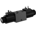
- Direct solenoid operated spool valve, standard version.
- Spool switching is by on off solenoids with a central tube and removable coil.
- Spring centered control spool.
- For mounting on industry standard surface port pattern to CETOP RP121 H-4.2-P02.
- Wet pin DC solenoids with removable coil and manual override.
- Manual override as option (push or screw-in type).
- Coil can be rotated through 360°.
- Available electrical connections: DIN 43650 – ISO 4400, AMP JUNIOR, DT04-2P (Deutsch), Free leads.
- Size 4
- Series 00
- Maximum operating pressure 310 bar (4500 psi)
- Maximum flow 25 l/min (6.6 gpm)
LC04-A
1)
For connectors ordering code see data sheet RE 18325-90.

The solenoid operated valves type L 50A0 provide 3-way or 4-way flow control, usually from port P to either port A or B, and the consequent flow return to T from B or A respectively.
The valves are composed by a central cast iron body (1) which mounts on industry standard surfaces where the flow ports and the installation holes are located; the central body houses the precisely machined directional control spool (2) which is held in the neutral or initial position by the return springs (4). One or two solenoids, composed by a central tube and a surrounding coil (5), are fitted to the body at the spool’s ends: when the coils are energized, their magnetic field develops a force on the oil immersed mobile plunger incorporated in the tube which pushes the control spool from the initial position into a shifted position where oil flow is allowed from P to either A or B.
With coils (5) de-energized, the control spool (2) returns to the central or initial position pushed by the washers (3) supported by the return springs (4).
The coils (5) are locked on the tube by threaded plastic nuts (6); the tube incorporates an externally reachable push rod (7) which can pushed for emergency spool shifting in case of electric failure.
These valves do not have return springs (4) for the directional control spool (2): the spool can shift between two positions, driven only by the magnetic force developed by the two solenoids (5), and, when the solenoids are not energized, the neutral position of the spool is not defined. The directional control spool holds a specific position only when one of the solenoids is maintained energized.
In these valves the directional control spool has two switched positions, each one with a mechanical detent. Shifting of the spool’s position is achieved by energizing one of the solenoids, but it is unnecessary to maintain the coil energized in order to keep the spool shifted.
Code
Voltage [V]
Connector type
Coil description
Marking
Coil Mat no.
OB 01
12 DC
EN 175301-803(Ex. DIN 43650)
D3601 12DC
12V DC
R901393412
OB 03
12 DC
AMP JUNIOR
D3603 12DC
12V DC
R901435507
OB 04
12 DC
AMP JUNIOR Horizontal
D3604 12DC
12V DC
R901395031
OB 07
12 DC
DEUTSCH DT 04-2P
D3607 12DC
12V DC
R901394397
OC 01
24 DC
EN 175301-803(Ex. DIN 43650)
D3601 24DC
24V DC
R901393577
OC 03
24 DC
AMP JUNIOR
D3603 24DC
24V DC
R901435494
OC 04
24 DC
AMP JUNIOR Horizontal
D3604 24DC
24V DC
R901395035
OC 07
24 DC
DEUTSCH DT 04-2P
D3607 24DC
24V DC
R901394399
OD 01
48 DC
EN 175301-803(Ex. DIN 43650)
D3601 48DC
48V DC
R901394117
OU 01
96 DC
EN 175301-803(Ex. DIN 43650)
D3601 96DC
96V DC
R901394229
AH 01
205 DC
EN 175301-803(Ex. DIN 43650)
D3601 205DC
205V DC
R901394231
For further versions (i.e. cable single lead) contact factory.
General
Valve element with 2 solenoids:
- 1.14 kg (2.5 lbs)
Valve element with 1 solenoid:
- 0.82 kg (1.7 lbs)
Valve installation positions:
- Unrestricted
Fluid Temperature:
- –30....+90 (-22....+194) (NBR seals)
Hydraulic
Maximum pressure at P, A and B ports:
- 310 bar (4500 psi)
Maximum pressure at T:
- 250 bar (3625 psi)
Maximum flow:
- 25 l/min (6.6 gpm)
Maximum flow when using spool type A201, A301, A401, A361, A471, G201,
G209:
- 18 l/min (4.7 gpm)
Hydraulic fluidGeneral properties: it must have physical lubricating and
chemical properties suitable for use in hydraulic systems such as, for
example:
- Mineral oil based hydraulic fluids HL (DIN 51524 part 1). For use of environmentally acceptable fluids (vegetable or polyglycol base) please consult us.
Fluid Temperature:
- –30....+100°C (-22....+212°F) (NBR seals)
Permissible degree of fluid contamination:
- ISO 4572: βₓ≥75 X=12...15 NAS 1638: class 9
Viscosity range:
- 5....420 mm²/s
Electrical
Voltage type:
- DC (AC only with RAC connection)
Voltage tolerance (nominal voltage):
- -10 .... +10%
Duty:
- Continuous, with ambient temperature ≤ 50°C (122°F)
Coil wire temperature not to be exceeded:
- 180°C (356°F)
Insulation class:
- H
Compliance with:
- Low Voltage Directive LVD 73/23/EC (2006/95/EC), 2004/108/EC
Coil weight with connection EN 175301-803:
- 0.18 kg (0.40 lbs)
Voltage:
- 12 V
- 24 V
- 48 V
- 96 V
- 205 V
Voltage type:
- DC
- DC
- DC
- DC
- DC
Power consumption:
- 20 W
- 20 W
- 20 W
- 20 W
- 20 W
Current (nominal at 20 °C (68 °F)):
- 1.62 A
- 0.84 A
- 0.45 A
- 0.21 A
- 0.01 A
Resistance (nominal at 20 °C (68 °F)):
 For applications with different specifications consult us.
- 7.4 Ω
- 28.4 Ω
- 106.4 Ω
- 451 Ω
- 2062 Ω
Spool Variant
Curve no.
P>T
P>A
P>B
A>T
B>T
A201, A301, A401, A361, A471, G201, G209
4
1
1
2
2
B201, B301, B401
5
5
7
7
B361, B471
5
5
8
8
C201, C301, C401, C361, C471, D201, D301, D401; D361, D471
6
6
6
8
8
E201, E301, E401, E361, E471, K201, K209, K301, K401
5
5
8
8
L201
5
5
8
7
L501
3
5
7
7
M201
3
3
7
6
M501
2
3
6
5
N201
3
3
N301
2
5
N401
5
2
N501
2
3
T301, T409
5
5
X301, Y301
3
5
8
6
X401, Y401
5
3
6
8
Measured with hydraulic fluid ISO-VG32 at 45° ±5 °C (113° ±9 °F); ambient temperature 20 °C (68 °F).
Spool Variant
Curve no.
A201; A301; A401; A361; A471; G201; G209
1
B201; B301; B401; B361; B471; C201; C301; C401; C361; C471; L201; L501; M201; M501
2
E201, E301, E401; E361; E471; D201, D301, D401; D361; D471; K201, K209; K301; K401; T301; T409
3
X301; X401; Y301; Y401
4
N201; N301; N401; N501
5
The performance curves here shown are applicable when oil flow is travelling in both directions, example P>A and B>T. In special circuit schemes the performance limits can be lower.
1
Solenoid tube O 16mm (0.63inch).
2
Blinding plug for 2 positions version.
3
Ring nut for coil locking O 26,5 mm (1,04inch).Torque 3 – 4 Nm (2.2 – 3.0 ft-lb).
4
Drilling specifications of standard mounting surface according to CETOP RP 121 H-4.2 4-P02.
5
Locking screws 3 pieces: UNI 5931 (ISO 4762) hexagon socket head cap screw M 5x25, recommended specific strength 8.8 class. Torque 5 ÷ 6 Nm (3.7÷4.4 ft-lbs).
6
Gap needed for connector removal.
7
Optional push-button type manual override for spool opening: it is pressure stuck to the ring nut for coil locking.Mat no. R930059524.
8
Optional screw type manual override for spool opening: it is screwed torque 6-7Nm (4.4-5.2 ft-lb) to the tube as replacement of the coil ring nut. Mat no. R930059561.
9
Identification label.