Compact Directional Valves - Non-compensated and Post-compensated - Fixation elements and Accessories ED Series

ED Accessories and fixation Elements

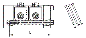
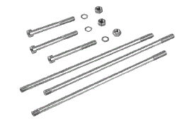
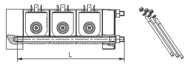
For 3 or more elements, the assembly kit is composed by 3 tie-rods, 3 washers and 3 nuts
Total flangeable elements
Screw or tie-rod length L mm (inch)
Tightening torque for tie rod on entry plate Nm (ft-lb)
Tightening torque for locking nut (opt.) Nm (ft-lb)
Tightening torque for screws or nuts Nm (ft-lb)
Reference code
Type
Material Number
1
80 (3.150)
N/A
N/A
17-18 (12,5-13,3)
K-2201
Screw
R933003721
2
125 (4.921)
N/A
N/A
17-18 (12,5-13,3)
K-2202
Screw
R933003722
3
185 (7.283)
17-23 (12,5-17)
5-6 (3,7-4,4)
17-18 (12,5-13,3)
K-2203
Tie-rod
R933003723
4
230 (9.055)
17-23 (12,5-17)
5-6 (3,7-4,4)
17-18 (12,5-13,3)
K-2204
Tie-rod
R933003724
5
275 (10.827)
17-23 (12,5-17)
5-6 (3,7-4,4)
17-18 (12,5-13,3)
K-2205
Tie-rod
R933003725
6
320 (12.598)
17-23 (12,5-17)
5-6 (3,7-4,4)
17-18 (12,5-13,3)
K-2206
Tie-rod
R933003726
7
365 (14.370)
17-23 (12,5-17)
5-6 (3,7-4,4)
17-18 (12,5-13,3)
K-2207
Tie-rod
R933003727
8
416 (16.378)
17-23 (12,5-17)
5-6 (3,7-4,4)
17-18 (12,5-13,3)
K-2208
Tie-rod
R933003728
9
460 (18.110)
17-23 (12,5-17)
5-6 (3,7-4,4)
17-18 (12,5-13,3)
K-2209
Tie-rod
R933003729
10
510 (20.079)
17-23 (12,5-17)
5-6 (3,7-4,4)
17-18 (12,5-13,3)
K-2210
Tie-rod
R933000000

RE18301-90-01

For 1 or 2 elements, the assembly kit is composed by 3 screws and 3 washers

RE18301-90-02
RE18301-90-03

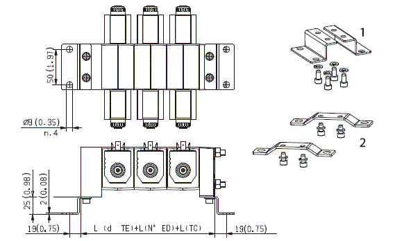
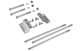
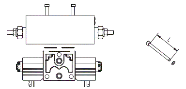
The kit is composed by 2 brackets, 4 screws and 4 washers.
Nr.
Type
Tightening torque Nm (ft-lb)
Material Number
1
K-2215
9-10 (6.64-7.37)
R933003730
2
K-2216
9-10 (6.64-7.37)
R933007089
RE18301-90-04

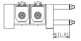
The assembly kit is composed by 4 screws and 4 washers.
Total flangeable elements
Screw or tie-rod length L mm (inch)
Tightening torque Nm (ft-lb)
Reference code
Material Number
1
60 (2.326)
5-6 (3.69-4.42)
K-2221
R933003731
2
120 (4.724)
5-6 (3.69-4.42)
K-2222
R933003732
3
175 (6.890)
5-6 (3.69-4.42)
K-2223
R933003733
RE18301-90-05

The spacers (code 44-00257012) are fitted in order to install longer tie-rods for future insertion of an extra directional element.


RE18301-90-06
Material description
Orifice I.D. mm (inch)
Material Number
50-04999
Closed
R933002917
50-05003
0,3 (0.012)
R933002922
50-05004
0,4 (0.016)
R933003398
50-05001
0,5 (0.020)
R933002920
50-05000
0,6 (0.024)
R933002919
50-05002
0,7 (0.028)
R933002921
50-0500
0,8 (0.031)
R933002918
50-05008
0,9 (0.035)
R933002923
50-0501
1,0 (0.039)
R933002924
50-05015
1,1 (0.043)
R933002925
50-0502
1,2 (0.047)
R933002926
50-05022
1,35 (0.053)
R933002927
50-0503
1,5 (0.059)
R933002928
50-05032
1,6 (0.063)
R933002930
50-05031
1,7 (0.067)
R933002929
50-0504
2,0 (0.079)
R933002931
50-0505
2,2 (0.087)
R933002933
50-05045
2,5 (0.098)
R933002932
50-0506
3,0 (0.118)
R933002934
50-0508
3,2 (0.126)
R933002935
50-0510
4,0 (0.157)
R933007391
50-0515
5,0 (0.197)
R933008462

RE18301-90-07
Material description
Orifice I.D. mm (inch)
Material Number
50-07000
Closed
R933002936
50-07020
0,8 (0.031)
R933002937
50-07021
1,0 (0.039)
R933007090
50-07022
1,1 (0.043)
R933007930
50-07023
1,2 (0.047)
R933007633
50-07024
1,4 (0.055)
R933007704
50-07030
1,6 (0.063)
R933002938
50-07031
1,7 (0.067)
R933007091
50-07040
2,0 (0.079)
R933002939
50-07043
2,25 (0.089)
R933009044
50-07045
2,5 (0.098)
R933007477
50-07047
2,75 (0.108)
R933002940
50-07050
3,0 (0.118)
R933002941
50-07056
3,5 (0.138)
R933009575
50-07057
3,75 (0.148)
R933007703
50-07060
4,0 (0.157)
R933007631
50-07070
5,5 (0.217)
R933007567
RE18301-90-08

To have information about the pressure drops on elements, see the (DELTA P-Q) curves of P>T of A201 circuit of ED1 (RE 18301-01) or ED2 (RE 18301-02) modular elements.


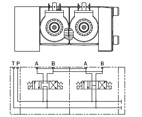
Flangeable elements with A and B ports in one side
RE18301-90-09

scheme 1

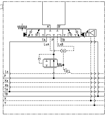
Also available flangeable elements with A and B ports in one side, oriented either toward the inlet (TE) side, or toward the outlet (TC) side (see Hydraulic symobol 1).


Flangeable elements with A and B ports in one side, and with an intermediate body for connection of A and P
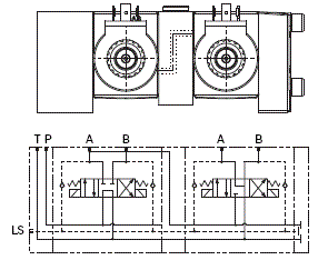
RE18301-90-10

scheme 2

For flangeable elements with A and B ports in one side there is also a flangeable body to connect the A port of one element to the P port of the following element (see Hydraulic symobol 2).