Compact Directional Valves - Non-compensated and Post-compensated - Intermediate elements ED Series

TI-C2

Description

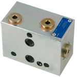
The sandwich plate design directional valve elements TI-C2- -… basically consist of a stackable housing with a 2 way compensator controlled by the LS pressure signal.

The normally open compensator maintains a constant pressure difference between the P1 (outlet) line and the LS pressure; the result is a constant oil flow to the P1 port for the downstream operators, independently from the working pressure.

The excess oil must be unloaded to tank through a relief valve.

The stackable housing is made of Yellow Zinc plated (Cr+3) Cast Iron.

General
Valve element TI-C2-__-:
  • 1.7 kg (3.75 lbs)
Fluid Temperature:
  • –20….+50 (-4….+122) (NBR seals)
Hydraulic
Maximum pressure:
  • 310 bar (4500 psi)
Maximum inlet flow:
  • 30 l/min (7.9 gpm)
Hydraulic fluid General properties: it must have physical lubricating and chemical properties suitable for use in hydraulic systems such as, for example:
  • Mineral oil based hydraulic fluids HL (DIN 51524 part 1). Mineral oil based hydraulic fluids HLP (DIN 51524 part 2). For use of environmentally acceptable fluids (vegetable or polyglycol base) please consult us.
Fluid Temperature:
  • –20….+80 °C (-4….+176 °F) (NBR)
Permissible degree of fluid contamination:
  • ISO 4572: βₓ≥75 X=12…15 ISO 4406: class 20/18/15 NAS 1638: class 9
Viscosity range:
  • Note: For applications with different specifications consult us
  • 5….420 mm²/s
RE18301-28-order

Symbol

RE18301-28-sym

Pressure function

RE18301-28-01

Compensated flow curves

RE18301-28-02
RE18301-28-dim
1
Flange specifications for coupling to ED intermediate elements.
2
For tie rod and tightening torque information see data sheet RE 18301-90.