Compact Directional Valves - Non-compensated and Post-compensated - Intermediate elements ED Series

TI-M412

Description

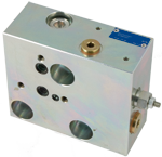
The adaptor elements TI-M412 -__ are employed to connect an ED directional valve assembly to a main control valve Rexroth M4-12.

These elements basically consist of body made of Yellow Zinc plated (Cr+3) steel which incorporates the following items:

  • a check valve on the P - P1 line.
  • a shuttle valve on the LS lines.
  • a relief valve on the un the LS line which controls the maximum pressure output from the pump.
  • a pressure compensated orifice which drains to tank the LS pressure by unloading a small regulated flow.
RE18301-29-01
General
Weight:
  • 6 kg (13.2 lbs)
Fluid Temperature:
  • –20….+50 (-4….+122)
Hydraulic
Maximum pressure:
  • 310 bar (4500 psi)
Max. flow at P1:
  • The max. rated flow depends from the directional control element.
Hydraulic fluid General properties: it must have physical lubricating and chemical properties suitable for use in hydraulic systems such as, for example:
  • Mineral oil based hydraulic fluids HL (DIN 51524 part 1). Mineral oil based hydraulic fluids HLP (DIN 51524 part 2). For use of environmentally acceptable fluids (vegetable or polyglycol base) please consult us.
Fluid Temperature:
  • -20….+80 °C (-4….+176°F) (NBR)
Permissible degree of fluid contamination:
  • ISO 4572: βₓ≥75 X=10…12 ISO 4406: class 19/17/14 NAS 1638: class 8
Viscosity range:
  • Note: For applications with different specifications consult us
  • 5….420 mm²/s
RE18301-29-order
RE18301-29-dim
1
Flange specifications for coupling to ED directional valve elements.
2
For tie rod and tightening torque information see data sheet RE 18301-90.
3
No. 2 threaded holes M10 for fixation.
4
No. 3 holes 10.5 mm dia. for assembling M4-12 directional valve elements.
5
LS port (locked by a G 1/4 plug).