Compact Motion Control Valves - Check and Metering Valves

E-VALVE 5.0

Ports D2, E1, E2, SC2, G1, G2, M1 to be drilled on request. Port identified with D1 and SC1 are not protected with calibrated orifice but in direct connection with pressure channels.

Description

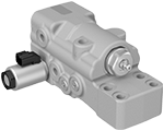
The electro hydraulic check and metering E-valve for excavators prevents uncontrolled lowering of the actuator in case of hose failure and provides the load holding when the joystick is released in neutral position. Lifting operations are performed with very limited pressure losses across the valve. The valve includes also a pressure relief stage (1) which prevents any overloads into the cylinder.

The actuation of the valve is performed by energizing the electro-proportional pilot stage (2) whose setting and characteristic curve are determined by changing the electrical parameters. Based on the two stages opening principle (2, 3), the valve provides flow metering from the cylinder to the main control valve and offers the possibility to change the behavior of the machine only by adjusting the pilot stage parameters. For safety reasons, the valve is directly mounted on the cylinder flange and provides a compact installation with the elimination of the pilot piping and the positioning of all hydraulic ports on the back surface. The valve is also equipped with a by-pass function (4) which can be used for emergency boom lowering in case of power supply failure.

Series E-valve

Maximum operating pressure: 420 bar (6090 psi)

Max. flow: 500 l/min. (132 gpm)


Main Field of Application

RE18309-24-01(2023-10-27)

Excavators

Material Handlers

Size 5.0

Note for applications outside these parameters, please consult us.

General:
Weight:
  • 9.30 kg (20.50 lbs)
Manifold material:
  • Zinc plated cast iron
Fluid Temperature:
  • -30....+110 (-22....+230)
Salt spray test:
  • 500 h
Hydraulic:
Max. operating pressure:
  • 420 bar (6090 psi)
Max. pressure at C-A ports:
  • 420 bar (6090 psi)
Max. pressure at L port:
  • 25 bar (362.6 psi)
Max. flow:
  • 500 l/min. (132 gpm)
Opening current range:
  • 600 - 1600 mA (Voltage 12 V) and 350 - 700 (Voltage 24 V)
Setting:
  • Cracking pressure of main stage (3) with 100 bar load pressure.
Fluid:
  • Mineral oil (HL, HLP) according DIN 51524
Fluid temperature range:
  • -30....+100°C (-22....+212°F)
Viscosity range:
  • 15....380 mm2/s
Permissible degree of fluid contamination:
  • Class 19/17/14 according to ISO 4406
Other technical data:
  • see data sheet 18350-50
Electrical:
Type of voltage:
  • DC Voltage
Standard Voltage:
  • 12 DC ± 15% V
  • 24 DC ± 15% V
Power:
  • 20 (cold coil at 20°C) W
  • 20 (cold coil at 20°C) W
Resistance at 20°C:
  • 2.3 ± 5% Ω
  • 11.5 ± 5% Ω
Resistance at max. hot valve (Rmax):
  • 3.8 Ω
  • 18.5 Ω
Max. current (Imax):
  • 1760 mA
  • 800 mA
Minimum terminal voltage to get Imax at Rmax:
  • 6.7 V
  • 14.5 V
Duty cycle ED:
  • 100%
  • 100%
Insulation class of coil:
  • H
  • H
Coil protection:
  • IP 69K
  • IP 69K
Coil weight:
  • 0.24 kg (0.53 lbs)
  • 0.24 kg (0.53 lbs)
Coil connector:
  • DT04-2P DEUTSCH
  • DT04-2P DEUTSCH
Recommended dither freq. (PWM):
  • 200 Hz
  • 200 Hz

Measured with hydraulic fluid ISO-VG46 at 36° ±2 °C (97° ±36 °F); ambient temperature 23 °C (73 °F).


RE18309-24-02(2023-10-27)

Δp = f (Q) Pressure drop - Flow rate characteristic Lifting (A->C)


RE18309-24-03(2023-10-27)

Δp = f (Q) Pressure drop - Flow rate characteristic Lowering (C->A), main stage (3) completely open.

RE18309-24-dim(2023-10-27)
Ports
Std. size
L
G1/4 - BSPP ISO 1179-1
Optional ports:D2, E1, E2, SC2, G1, G2, M1 - to be drilled on request
G1/4 - BSPP ISO 1179-1

Single Operation

RE18309-24-04(2023-10-27)

Parallel Operation

RE18309-24-05(2023-10-27)
RE18309-24-order(2023-10-27)
Flange seal kit
E00000000000002 (R930004532) C flange 3/4 SAE 6000
E00000000000003 (R930004533) C flange 1 SAE 6000
Type
Material number
0GE5300G0242000
R930083563
0GE5301G0242000
R930083564
0GE5302G0242000
R930083566