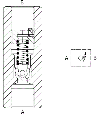
Sleeve for Line Mounting - Directional Control Valves - Check

LCA (7 series - 10 series)

RE18316-38-01(2023-11-01)
Description

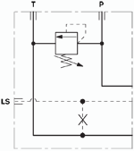
Flow is always allowed to pass from A to B when pressure at A rises above the spring bias pressure and the poppet is pushed from the seat. The spring load is adjustable by turning the internal ring nut with a 4 mm allen wrench for LCA7 (5 mm allen wrench for LCA10): screwing down increases the spring load and increases the cracking pressure (in order to turn the Ring Nut, loosen first the little locking screw with a 1.5 mm Allen wrench; tighten it again once the spring load is adjusted). The valve is normally closed (checked) from B to A.

RE18316-38-02(2023-11-01)

Steel body, zinc plated

Δp curves vs. flow in “A-B” free flow direction. For cracking pressure range refer to the specific table.
General:
Code:
  • Pressure P max bar (psi)
LCA 7:
  • 350 (5000)
LCA 10:
  • 350 (5000)
RE18316-38-dim(2023-11-01)

Note: when ordering the valves Factory set please, specify the desired cracking pressure expressed in “bar”. Without such specification, the valves will be supplied non adjusted.

RE18316-38-order(2023-11-01)
Code
Ports size A-B
L mm (inches)
Hex mm (inches)
Hex 1 mm (inches)
Hex 2 mm (inches)
LCA 7
G 1/4
73 (2.87)
19 (0.75)
4 (0.16)
1.5 (0.06)
LCA 10
G 3/8
73 (2.87)
24 (0.95)
5 (0.20)
1.5 (0.06)