Sleeve for Line Mounting - Directional Control Valves - Check

VUH-MF

RE18316-33-01(2023-11-27)
RE18316-33-02(2023-11-27)

Δp curves vs. flow in “A-B” free flow direction

As seen on the diagram, the cracking pressure is very low.

  • Very compact design and inline mounting for space saving.
  • Mounting position is unrestricted.
  • Three sizes provide great adaptability to the system.
  • The inserted flow regulator cartridge can be purchased separately for easy service or for modifications to the original flow adjustment (ref. Catalogue RE 18329-61).
Description

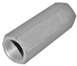
This valve is composed by a sleeve with an inserted poppet type check cartridge type VUH1.

Flow is always allowed to pass from A to B when pressure at A rises above the spring bias pressure and the ball is pushed from the seat. The valve is normally closed (checked) from B to A.

The inserted cartridge can be screwed-in or screwed-out with an Allen type key 6 or 8 mm, depending from the cartridge size.

VUH1 Code
Ports A-B
Pressure P max bar (psi)
Flow Q max l/min (gpm)
Weight kg (lbs)
0T.U5.01.00.09.00
G 1/4
350 (5000)
22 (6)
0.01 (0.02)
0T.U5.01.00.02.00
G 3/8
350 (5000)
50 (13)
0.02 (0.04)
0T.U5.01.00.03.00
G 1/2
350 (5000)
80 (21)
0.02 (0.04)

Steel body, zinc plated

RE18316-33-dim(2023-11-27)
Z
Cracking pressure bar (psi)
00
< 0.5 (< 7)
RE18316-33-order(2023-11-27)
Y
Ports A-B
L mm (inches)
Hex mm (inches)
Sleeve code
09
G 1/4
48 (1.89)
19 (0.75)
OC.51.02.001
02
G 3/8
52 (2.05)
22 (0.87)
OC.51.02.002
03
G 1/2
62 (2.44)
27 (1.06)
OC.51.02.003
RE18316-33-03(2023-11-27)
VUH1 code thread
ØF
L
L1
L2
ØD
Ød
Inst. torque
Tool code
0T.U5.01.00.09.00 G 1/4
11.3 (0.45)
120 (4.72)
110 (4.33)
60 (2.36)
8.5 (0.34)
2.2 (0.09)
6 Nm (4)ft-lb
AVA17
0T.U5.01.00.02.00 G 3/8
14.9 (0.59)
120 (4.72)
108 (4.25)
80 (3.15)
10.8 (0.43)
3 (0.12)
6Nm (4)ft-lb
AVA17-01
0T.U5.01.00.03.00 G 1/2
18.6 (0.73)
120 (4.72
108 (4.25)
80 (3.15)
14.2 (0.56)
3.8 (0.15)
10Nm (7)ft-lb
AVA17-02

More details on RE 18329-61 catalogue.