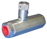
Sleeve for Line Mounting - Flow Control Valves - Flow regulator

VCST (G 1/4)

RE18316-18-02(2023-11-27)
Description

This pressure compensated flow regulator controls the oil flow from B to A, and prevents it from exceeding the adjusted value regardless of working pressure, while establishing a minimum pressure differential of approximately 5 bar (75 psi) between the two ports. The valve is available in different sizes and versions for different flow ranges, as specified by the tables of the Technical data, Dimensions and Performance diagrams. The fine setting of the output flow at A can be achieved by rotating the hand knob which can be locked in position by the locking nut in order to prevent inadvertent changes. Unrestricted reverse flow “A-B” is permitted through a check valve with zero cracking pressure, regardless of valve adjustment.

RE18316-18-03(2023-11-27)
Code
Pressure P max bar (psi)
Flow Q l/min (gpm)
Weight kg (lbs)
VCST 14
 
4 - 10
VCST 14 P
250 (3600)
(1 - 3)
0.35 (0.77)
VCST 14 PP
1 - 4
 
(0.3 - 1)

Steel body, zinc plated

RE18316-18-dim(2023-11-27)
 
VCST 14
VCST 14 P
VCST 14 PP
knurled knob
x
 
x
hand knob
 
x
Port size A-B
G 1/4
L mm (inches)
87.5 (3.45)
L3 mm (inches)
8.5 (0.34)
L2 mm (inches)
79 (3.11)
L1 mm (inches)
51 (2.01)
Hex mm (inches)
27 (1.06)

The “ I ” version is stainless steel made.

R932500617

  • Compact design and inline mounting for space saving.
  • Flow setting can be locked by the locking nut.
  • Mounting position is unrestricted.
  • Zero cracking pressure for free reverse flow “A-B”.
  • Three sizes, each with hand knob or knurled hand knob, provide great adaptability to the system.

The VCST is a normally open, two ports, restrictive type flow regulator, with incorporated check valve for free reverse flow. Typical applications are the control of the maximum speed of an actuator (cylinder or motor), which is achieved by regulating the maximum flow A into or out from the actuator (meter-IN, or meter-OUT). The maximum flow, and consequently the maximum actuator speed, will vary slightly with changes in fluid viscosity, but will be largely independent from the load and from the working pressure. If the valve is used to control the flow from a constant flow line, only the regulated flow will pass through the valve; any excess flow will normally be forced out of the line and delivered to tank through the system relief valve.

RE18316-18-order(2023-11-27)