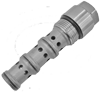
Cartridge Valves - Directional Control Valves - Logic elements

VCSQ-16A

RE18321-82-01(2023-11-07)
Description

Flow is normally allowed from 4 to 3. When pilot pressure at 1 rises above the combined pressure of the spring bias, plus pressure at 4, the valve shifts to block flow between 3 and 4, while diverting flow from 1 to 2. A constant pressure drop is maintained across a fixed (or variable) orifice upstream of 4 when installed and piloted per the diagram above. In this case, flow priority is given to 3, with flow in excess of the orifice differential requirement being by-passed to 2.

¹) Only external seals for 10 valves

General:
Max. operating pressure:
  • 350 bar (5000 psi)
Max. flow:
  • 200 l/min. (53 gpm)
Max. priority flow:
  • 120 l/min. (32 gpm)
Flow maintenance:
  • ± 10%
Fluid temperature range:
  • -30 to 100 °C (-22 to 212 °F)
Installation torque:
  • 108 - 122 Nm (80 - 90 ft-lbs)
Weight:
  • 0.75 kg (1.65 lbs)
Cavity:
  • CA-16A-4N (see data sheet 18325-70)
Lines bodies and standard assemblies:
  • Please refer to section “Hydraulic integrated circuit” or consult factory
Seal kit¹):
  • Code: RG16A4010530100
  • material no: R930000973
Fluids:
  • Mineral-based or synthetics with lubricating properties at viscosities of 10 to 500 mm²/s (cSt)
Recommended degree of fluid contamination:
  • Nominal value max. 10µm (NAS 8) / ISO 4406 19/17/14
Installation:
  • No restrictions
Other Technical Data:
  • See data sheet 18350-50
RE18321-82-02(2023-11-07)
RE18321-82-order(2023-11-07)
RE18321-82-dim(2023-11-07)