


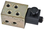
- 8 way 2 position valve.
- Directional spool valve with direct solenoid control.
- Normally used to set up the remote control (ISO – SAE) in the earth moving machine.
- Control spool operated by solenoid, with easily removable coil fastened by a ring nut.
- Wet pin tube for DC coil, with push rod for mechanical override in case of voltage shortage- Unrestricted 360° orientation of DC coil.
- Control spool held in normal position by return spring.
- Connectors available: DIN 43650 – ISO 4400, AMP Junior, DT04-2P (Deutsch), Free leads.
- Size 2
- Series 00
- Maximum operating pressure 210 bar (3045 psi)
- Maximum flow 10 l/min (2.6 gpm)
- Ports G 1/4 - SAE 4
VS570-VS575
A valve basically consists of a housing (1), a control spool (2), one or two solenoid (3), and a return spring (4).
L76510BY..
If the solenoid is energized, the spool goes from position “0” t o position “b” .
With the coil de-energized, the return spring (3) pushes back the spool (2) and holds it in position “0”.
The coil (6) is fastened to the tube by the ring nut (7).
L76510CY..
If the solenoid “a” is energized, the spool goes from position “a” t o position “b”. The position “b” is held by the detent (8).
The return to position “a” is obtained energising the solenoid “b”.
The coil (6) is fastened to the tube by the ring nut (7).
![]() For applications with different specifications consult us
For applications with different specifications consult us
Code
Voltage [V]
Connector type
Coil description
Marking
Coil Mat no.
OB 01
12 DC
EN 175301- 803(Ex. DIN 43650)
C3601 12DC
12 DC
R933000044
OB 03
12 DC
AMP JUNIOR
C3603 12DC
12 DC
R933000047
OB 04
12 DC
AMP JUNIOR Horizontal
C3604 12DC
12 DC
R933002913
OB 07
12 DC
DEUTSCH DT 04-2P
C3607 12DC
12 DC
R933000048
OB 31
12 DC
Cable 350 mm long
C3631 12DC
12 DC
R933000045
AD 01
13 DC
EN 175301-803(Ex. DIN 43650)
C3601 13DC
13 DC
R933000051
AD 07
13 DC
DEUTSCH DT 04-2P
C3607 13DC
13 DC
R933000049
OC 01
24 DC
EN 175301-803(Ex. DIN 43650)
C3601 24DC
24 DC
R933000053
OC 03
24 DC
AMP JUNIOR
C3603 24DC
24 DC
R933000057
OC 04
24 DC
AMP JUNIOR Horizontal
C3604 24DC
24 DC
R933002914
OC 07
24 DC
DEUTSCH DT 04-2P
C3607 24DC
24 DC
R933000058
OC 31
24 DC
Cable 350 mm long
C3637 24DC
24 DC
R933000055
AC 01
27 DC
EN 175301-803(Ex. DIN 43650)
C3601 27DC
27 DC
R933000056
AC 07
27 DC
DEUTSCH DT 04-2P
C3607 27DC
27 DC
R933000050
OD 01
48 DC
EN 175301-803(Ex. DIN 43650)
C3601 48DC
48 DC
R933000059
OD 04
48 DC
AMP JUNIOR Horizontal
C3604 48DC
48 DC
R933002915
OE 01
110 DC
EN 175301-803(Ex. DIN 43650)
C3601 110DC
110 DC
R933000061
General:
Valve weight CY:
- 1.88 kg (4.15 lbs)
Valve weight BY:
- 2.18 kg (4.8 lbs)
Mounting position:
- unrestricted
Fluid Temperature:
- –20....+50 (-4....+122) (NBR seals)
Hydraulic:
Maximum pressure:
- 210 bar (3045 psi)
Maximum flow:
- 10 l/min (2.64 gpm)
Hydraulic fluidGeneral properties: it must have physical lubricating and
chemical properties suitable for use in hydraulic systems such as, for
example:
- Mineral oil based hydraulic fluids HL (DIN 51524 part 1). For use of environmentally acceptable fluids (vegetable or polyglycol base) please consult us.
Fluid Temperature:
- –20....+80 °C (-4....+176 °F) (NBR seals)
Permissible degree of fluid contamination:
- ISO 4572: βx ≥ 75 X = 12...15 NAS 1638: class 9
Viscosity range:
- 5....420 mm²/s
Internal leakage with 100 bar (1450 psi):
- min.10 cc/min (0.61 in³/min) max. 20 (1.2)
Electrical:
Voltage type:
- DC
Voltage tolerance (nominal voltage):
- -10 .... +10 %
Duty:
- Continuous (100%), with ambient temperature ≤ 50°C (122°F)
Coil wire temperature not to be exceeded:
- 150 °C (302 °F)
Insulation class:
- H
Compliance with:
- Low Voltage Directive LVD 73/23/EC (2006/95/EC), 2004/108/EC
Coil weight with connection EN 175301-803:
- 0.215 kg (0.44 lbs)
Voltage:
- 12 V 13 V 24 V 27 V 48 V 110 V
Voltage type:
- DC DC DC DC DC DC
Power consumption:
- 26 W 26 W 26 W 26 W 26 W 26 W
Current (nominal at 20 °C (68 °F)):
- 2.15 A 2.00 A 1.10 A 1.00 A 0.54 A 0.27 A
Resistance (nominal at 20 °C (68 °F)):
- 5.5 Ω 6.5 Ω 22 Ω 28 Ω 89 Ω 413 Ω
Scheme
Curve n.
A1>P1
B1>T1
A2>P2
B2>T2
A1>T1
B1>P1
A2>T2
B2>P2
BY-CY
2
1
2
1
2
3
2
3
Measured with hydraulic fluid ISO-VG32at45° ±5 °C (113° ±9 °F); ambient temperature 20 °C (68 °F).
Scheme
Curve No.
BY
1
CY
2
The performance curves are measured with flow going across and caming back.
1
Solenoid tube Ø 14 mm (0,55 inch).
3
Ring nut for coil locking Ø 20,4 mm (0.8 inch).Torque 3 – 4 Nm (2.2 – 3.0 ft-lb).
4
Two through holes for installation. Recommended screws M8 with strengt class DIN 8.8.
5
Hydraulic Ports (G1/4- SAE4).
6
Minimum clearance needed for connector removal.
7
Identification label.
Measure
VS570
VS575
L1
33.8 (1.33)
30.8 (1.21)
L2
59.4 (2.33)
56.4 (2.22)