Compact Directional Valves - Non-compensated and Post-compensated - Intermediate elements ED Series

TI-04

Description

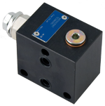
The intermediate elements TI-04-__- are designed to be fitted between two directional valve elements. Different hydraulic layout can be choice with different ordering codes.

Material: the body is made of black anodized Aluminium (AL), or of yellow Zinc plated (Cr+3) Cast Iron (CI).

General
Weight TI-04-00-AL:
  • 0.74 kg (1.63 lbs)
Weight TI-04-01-AL:
  • 0.84 kg (1.85 lbs)
Weight TI-04-02-AL-..-..:
  • 1.08 kg (2.38 lbs)
Weight TI-04-00-CI:
  • 1.10 kg (2.42 lbs)
Weight TI-04-03-CI:
  • 1.33 kg (2.93 lbs)
Ambient temperature:
  • –20....+50 (-4....+122) (NBR seals)
Hydraulic
Maximum inlet flow:
  • 50 l/min (13.2 gpm)
Maximum pressure TI-Aluminium:
  • 250 bar (3625 psi)
Maximum pressure TI-Cast Iron:
  • 310 bar (4495 psi)
Hydraulic fluid General properties: it must have physical lubricating and chemical properties suitable for use in hydraulic systems such as, for example:
  • Mineral oil based hydraulic fluids HL (DIN 51524 part 1). Mineral oil based hydraulic fluids HLP (DIN 51524 part 2). For use of environmentally acceptable fluids (vegetable or polyglycol base) please consult us.
Fluid Temperature:
  • –20....+80 °C (-4....+176 °F) (NBR)
Permissible degree of fluid contamination:
  • ISO 4572: βₓ≥75 X=10...12 ISO 4406: class 19/17/14 NAS 1638: class 8
Viscosity range:
  • Note: For applications with different specifications consult us
  • 5....420 mm²/s
RE18301-27-order

Symbol

RE18301-27-sym

RE18301-27-dim1
1
Flange specifications for coupling to ED intermediate elements.
2
For tie rod and tightening torque information see data sheet RE 18301-90.
3
Identification label.
4
Test point M(G 1/4) for pressure gauge connection.
5
Flow regulator cartridge ST-C-06.

RE18301-27-dim2
1
Flange specifications for coupling to ED intermediate elements.
2
For tie rod and tightening torque information see data sheet RE 18301-90.
3
Identification label.
4
Test point M(G 1/4) for pressure gauge connection.
5
Electrical valve 40 l/min (10,57 gpm).

RE18301-27-dim3
1
Flange specifications for coupling to ED intermediate elements.
2
For tie rod and tightening torque information see data sheet RE 18301-90.
3
Identification label.
4
Test point M(G 1/4) for pressure gauge connection.
5
Regulated flow range 0.2÷30 l/min (0.05÷7,92 gpm).