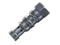
Cartridge Valves - Load Holding Valves - Counterbalance - Counterbalance standard

VBSN-08U-TF

RE18319-98-01(2023-11-07)
Description

When pressure at 2 rises above the spring bias pressure, the check seat is pushed away from the piston and flow is allowed from 2 to 1. When load pressure at 1 rises above the pressure setting, the direct-acting, differential area relief function is activated and flow is relieved from 1 to 2. With pilot pressure at 3, the pressure setting is reduced in proportion to the stated ratio of the valve, until fully open with free-flow from 1 to 2. The spring chamber is drained to 2, and any back-pressure at 2 is additive to the pressure setting in all functions.

Pressure setting: at least 1.3 times the load induced pressure.

1) At 70% of pressure setting

2) Only external seals for 10 valves

General:
Max. operating pressure:
  • 350 bar (5000 psi)
Max. flow:
  • 60 l/min (16 gpm)
Max. internal leakage 1):
  • 5 drops/min.
Fluid temperature range:
  • -30 to 100 °C (-22 to 212 °F)
Installation torque:
  • 40-50 Nm (30-37 ft-lbs)
Weight:
  • 0.18 kg (0.39 lbs)
Cavity:
  • SUN T11-A
Lines bodies and standard assemblies:
  • Please refer to section “Hydraulic integrated circuit” or consult factory
Seal kit²:
  • Code: RG08U9020110100
  • material no: R901193388
Fluids:
  • Mineral-based or synthetics with lubricating properties at viscosities of 10 to 500 mm²/s (cSt)
Recommended degree of fluid contamination:
  • Nominal value max. 10µm (NAS 8) / ISO 4406 19/17/14
Installation position:
  • No restrictions
Other Technical Data:
  • See data sheet 18350-50
RE18319-98-02(2023-11-07)
RE18319-98-order(2023-11-07)
RE18319-98-dim(2023-11-07)