Compact Directional Valves - Non-compensated and Post-compensated - Directional elements ED Series

ED-LV

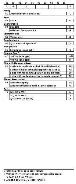
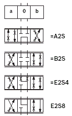
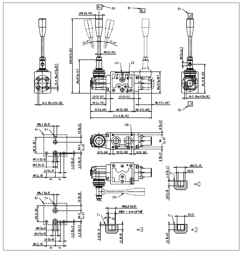
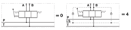
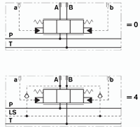
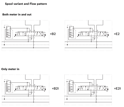
Valve elements 4 ways 3 positions.

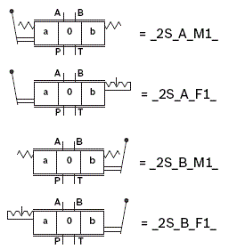
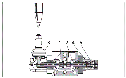
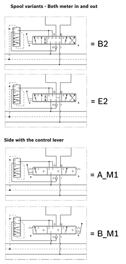
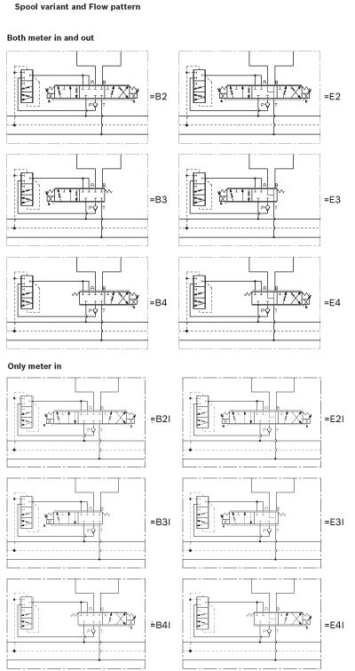
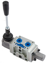
Control spools manual operated by hand lever.

Control spool with return spring or mechanical detent for all three positions.

Size 6

Series 00

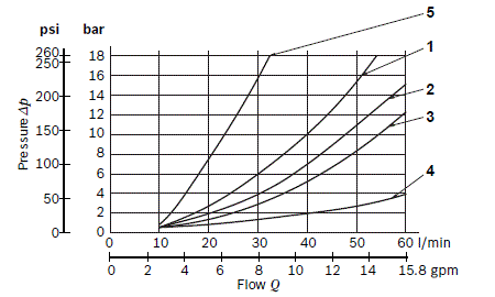
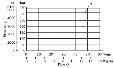
Maximum operating pressure 310 bar (4500 psi)

Maximum flow 60 l/min (15.8 gpm)

Port connections G 3/8 - G 1/2 - SAE8

RE18301-08-order
1)
Only meter in for E2S8 spool variant
2)
With ∆p (P > T) 10 bar (145 psi), corresponding approx. to ∆p P>A,B 5 bar (73 psi).
3)
Available only for B_, E_ spool variants.
RE18301-08-sym
RE18301-08-spool
RE18301-08-side
RE18301-08-functional

The sandwich plate design directional valve elements L8_1... are compact manual operated valves which control the start, the stop and the direction of the oil flow.

These elements basically consist of a stackable housing (1) with a control spool (2), a block with the control lever (3), and a spring housing (4) with a return spring (5).

The hand operated lever moves the control spool (2) from its neutral-central position “0” to the required position “a” or “b”, and the required flow from P to A (with B to T), or P to B (with A to T) is achieved.

Type L8_L1_2S_ __M100 is the valve version in which the return spring (5) brings the spool back to neutral-central position “0” when the manual lever is not operated.

The valve is available with a choice of spool variants (refer to page 2).

Type L8_L1_2S_ __F100 is the valve version with mechanical detent in which the control spool (2) stays in anyone of the 3 achieved positions “0”, “a” or “b” when the lever is left free. With this valve, the oil delivery can continue without any action on the lever.

Also this version is available with a choice of spool variants (refer to page 2).

Special types of control are available upon request.

General:
Valve element weight:
  • 1.55 kg (3.42 lbs)
Mounting position:
  • kg (lbs) Unrestricted
Fluid Temperature:
  • -20....+50 (-4....+122) (NBR seals)
Hydraulic:
Maximum pressure at P, A and B ports:
  • 310 bar (4500 psi)
Maximum pressure at T:
  • 160 bar (2320 psi)
Maximum inlet flow:
  • 60 l/min (15.9 gpm)
Nominal flow with DP P>T = 10 bar (145 psi):
  • 10, 20, 30 l/min (2.64, 5.28, 7.9 gpm)
Hydraulic fluidGeneral properties: it must have physical lubricating and chemical properties suitable for use in hydraulic systems such as, for example:
  • Mineral oil based hydraulic fluids HL (DIN 51524 part 1). For use of environmentally acceptable fluids (vegetable or polyglycol base) please consult us.
Fluid Temperature:
  • -20....+80°C (-4....+176°F) (NBR seals)
Permissible degree of fluid contamination:
  • ISO 4572: βₓ≥75 X=12...15 NAS 1638: class 9
Viscosity range:
  • Note: For applications with different specifications consult us
  • mm²/s 5 420
RE18301-08-02s
Spool Variant
Curve no.
P>A
P>B
A>T
B>T
P>T
B2S8, E2S8
2
2
4
4
-
A2S8
3
3
3
3
1
B2S4, E2S4
1
1
5
5
-

Measured with hydraulic fluid ISO-VG32 at 45° ±5 °C (113° ±9 °F); ambient temperature 20 °C (68 °F).

RE18301-08-per-limits
Spool Variant
Curve no.
A2S8, B2S8, E2S8, B2S4, E2S4
1
RE18301-08-min-flow
RE18301-08-dim
4
Flange specifications for coupling to ED intermediate elements with ports G 3/8.
5
For tie rod and tightening torque information see data sheet RE 18301-90.
6
Flange specifications for coupling to ED intermediate elements with ports G 1/2 (SAE 8).
7
A and B ports.
8
Side with the control lever (Standard is side A).
9
Hand lever orientation.
10
Hand lever orientation for packing and shipment.
11
Identification label.
12
LS channel (only for versions L84…).
13
Four threaded holes for fitting a secondary flangeable elements:- M5 holes on versions with ports G 3/8.- M6 holes on versions with ports SAE 8.- Without when the ports is G 1/2.