Compact Directional Valves - Non-compensated and Post-compensated - Directional elements EDC Series

EDC-IP

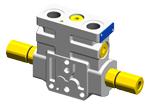
  • Valve element with direct proportional flow sharing control.
  • It can achieve the simultaneous activation of different actuators by distributing the available flow proportionally to the speeds selected by the operator.
  • All simultaneous movements go on at the same reciprocal speed also in case of flow shortage.
  • Hydraulically direct operated spool.
  • Hydraulic operating element bolted on.
  • Hydraulic operating element available with inlet port: G1/4 DIN3852; 9/16-18 UNF 2-B.
  • The control spool is held in the central position by return springs.
  • Size 6
  • Series 00
  • Maximum operating pressure 310 bar (4500 psi)
  • Maximum flow at 14 bar (203 psi) 50 l/min (13.2 gpm)
  • Maximum flow at 18 bar (261 psi) 58 l/min (15.3 gpm)
  • Ports connections planned G 3/8 - G 1/2 - SAE8 and Modular

NEW spool position sensor available for this valve. See RE18300-30

RE18301-14-order
RE18301-14-sym
RE18301-14-01
RE18301-14-02

The sandwich plate design directional valve elements L85P5... are compact direct hydraulic operated pressure compensated proportional valves which control the start, the stop, the direction and the quantity of the oil flow, with FLOW SHARING principle. These elements basically consist of a stackable housing (1) with a control spool (2), two hydraulic operating blocks (4), and two return spring return (3).

The hydraulic pressure in one of the blocks (4) pushes the control spool (2) from its neutral-central position "0" to the required end position "a" or "b". When the spool is shifted and the metering notch is open, flow delivery starts and is controlled by a 3 way pressure compensator followed by a check valve for each port A and B.

The compensator, balanced by the LS pressure at the opposite end, lifts up and unloads a regulated flow which is sent to the A (or B) port through the relevant check valve; at the same time the opposite port allows oil return to tank. LS pressure reaches the compensator “dead end” directly from the A or B port, while the check valves lock eventual pressure oscillations which could affect the compensator function.

When the pressure decrease in one of the block (4), the return spring (3) pushes the spool thrust washer back against the housing and the spool returns in its neutral-central position.

General:
Valve element with 2 hydraulic controls:
  • 3.05 kg (6.72 lbs)
Fluid Temperature:
  • –20....+50 (-4....+122) (NBR seals)
Hydraulic:
Maximum pressure at P, A and B ports:
  • 310 bar (4500 psi)
Maximum pressure at T to prevent damages:
  • 100 bar (1450 psi)
Reccomended maximum pressure at T during operation:
  • 10 bar (145 psi)
Max. pilot pressure:
  • 35 bar (508 psi)
Min. pilot pressure:
  • refer to page 6
Max. regulated flow at 14 bar (203 psi):
  • 50 l/min (13.2 gpm)
Max. regulated flow at 18 bar (261 psi):
  • 58 l/min (15.3 gpm)
E-schemes flow pattern symmetrical closed pass in the neutral position (connection from A to T and B to T):
  • Approx. 2% of the nominal cross-section
Hydraulic fluidGeneral properties: it must have physical lubricating and chemical properties suitable for use in hydraulic systems such as, for example:
  • Mineral oil based hydraulic fluids HL (DIN 51524 part 1). For use of environmentally acceptable fluids (vegetable or polyglycol base) please consult us.
Fluid Temperature:
  • –20....+80°C (-4....+176°F) (NBR seals)
Permissible degree of fluid contamination:
  • ISO 4572: βₓ≥75 X=10...12 NAS 1638: class 8
Viscosity range:
  • Note: Note
  • 20....380 (optimal 30....46) mm²/s
For applications with different specifications consult us:
RE18301-14-03

The curves refer to the spool fully open.

Measured with hydraulic fluid ISO-VG32 at 45° ±5 °C (113° ±9 °F); ambient temperature 20 °C (68 °F).

RE18301-14-04
RE18301-14-05
RE18301-14-06
RE18301-14-07

The curves refer to the spool fully open.

Measured with hydraulic fluid ISO-VG32 at 45° ±5 °C (113° ±9 °F); ambient temperature 20 °C (68 °F).

RE18301-14-dim1
1
Hydraulic operating element available with inlet port: G1/4 DIN3852; 9/16-18 UNF 2-B (SAE6)
2
Flange specifications for coupling to ED intermediate elements.
3
For tie rod and tightening torque information see data sheet RE 18301-90
4
A and B ports.
5
Identification label.
6
Four threaded holes M5 deepth 12mm [0.47 inch] for fitting a secondary flangeable element. Bolts M5 with recommended strength class DIN8.8: torque 5-6 Nm[3.6-4.4 ft-lb] (only for version with modular secondary valves).