Compact Directional Valves - Non-compensated and Post-compensated - Flangeable elements ED Series

EDM-VB

RE18301-43-01
Description

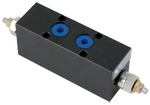
The secondary flangeable elements EDM-VB-__ can be interfaced and bolted on top of the A and B ports of the ED elements of the Directional Valve Assembly.

They incorporate one or two Cross Piloted Counterbalance Valves which allow free flow toward the A and B outlet ports, and lock in a leak free mode the flow returning from the actuator. Pilot pressure in the opposite line reduces the pressure setting of the counterbalance valve in proportion to the pilot ratio (4:1) until opening and allowing the flow return from the actuator.

The pressure setting should be at least 1,3 times the highest expected load.

Depending on the version selected (02AB, 020A or 020B), the counterbalance function can be double-acting or singleacting, upstream or downstream, in both A and B ports, or in A port only, or in B port only (see hydraulic symbols).

The body of the EDM-VB elements is made of Black Anodized Aluminium. Hydraulic Ports A and B are size G 3/8.

General
Weight of manifold, with two counterbalance valves EDM-VB-AB:
  • 1.2 kg (2.65 lbs)
Weight of manifold, with one counterbalance valve EDM-VB-0A:
  • 1.02 kg (2.24 lbs)
Fluid Temperature:
  • –20....+50 (-4....+122) (NBR seals)
Hydraulic
Maximum pressure:
  • 250 bar (3625 psi)
Maximum flow:
  • 40 l/min (13.2 gpm)
Hydraulic fluid General properties: it must have physical lubricating and chemical properties suitable for use in hydraulic systems such as, for example:
  • Mineral oil based hydraulic fluids HL (DIN 51524 part 1). Mineral oil based hydraulic fluids HLP (DIN 51524 part 2). For use of environmentally acceptable fluids (vegetable or polyglycol base) please consult us.
Fluid Temperature:
  • –20....+80 °C (-4....+176 °F) (NBR)
Permissible degree of fluid contamination:
  • ISO 4572: βₓ≥75 X=10...12 ISO 4406: class 19/17/14 NAS 1638: class 8
Viscosity range:
  • Note: For applications with different specifications consult us
  • 5....420 mm²/s
RE18301-43-order
RE18301-43-sym
RE18301-43-02
Pressure drop
Curve no.
Fully piloted
1
Through check valve
2

Measured with hydraulic fluid ISO-VG32 at 45° ±5 °C (113° ±9 °F); ambient temperature 20 °C (68 °F).

RE18301-43-Dim
1
Four through holes Ø 5.5 mm (0.217 inch) for screws and tightening torques see data sheet RE 18301-90.
2
Counterbalance valve with screw type adjustment.
3
A1 and B1 ports for the actuator.
4
Identification label.