Compact Motion Control Valves - Check and Metering Valves

A-VBCN-22-SX-RE-FC

RE18309-17-01(2023-10-26)
Description

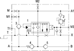
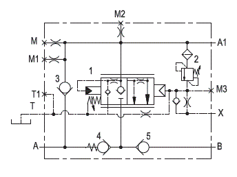
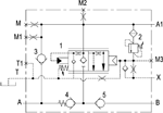
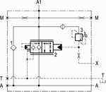
Unrestricted upstream flow (A – A1) to the cylinder is possible through the check valve (3), while downstream flow (A1 – A ,or A1 – B) is locked by the leak free main spool (1) which is held closed by the spring and by the load induced pressure. With pilot pressure at X (joystick), the spool (1) is first vented to tank then it is remotely controlled and it slides to provide fine metering for the downstream flow; after the initial venting, the pilot pressure required to move the spool is load independent. The return flow (A1 – A) is slightly pressurized by the check valve (4) and is available to re-fill the opposite end of the cylinder through the check valve (5) and port (B), in order to prevent cavitation. The valve includes a small relief cartridge (2) which senses the A1 pressure (load induced) and opens under overload or shock conditions in order to pilot fully open the main spool (1): this allows any excess of pressure at A1 to be relieved downstream through A. For better safety and compact assembly, the A1 port is flanged (gasket mounted) directly on the actuator.

Note: for applications outside these parameters, please consult us.
¹) Seals for 10 valves.

General:
Max. operating pressure:
  • 420 bar (6000 psi)
Max. flow:
  • 400 /min. (106 gpm)
Weight:
  • 26 kg (57.3 lbs)
Flange seal kit ¹):
  • E00000000000003 (R930004533)
Manifold material:
  • Zinc plated steel
Fluid:
  • Mineral oil (HL, HLP) according DIN 51524
Fluid temperature range:
  • -30 °C to 100 (-22 to 212 °F)
Viscosity range:
  • 10 to 500 mm²/s (cSt)
Recommended degree of fluid contamination:
  • Class 19/17/14 according to ISO 4406
The Tank vented port must be connected to a “low pressure tank line” (to the joystick tank line, or to tank directly).:
The restricted “M” port must be connected to a “pressure equalizing line” in case of 2 valves fitted to 2 twin cylinders, and may be used as “outlet to tank” for emergency boom lowering in case of pilot pressure failure.:
This valve with specific adjustments, it can become part of load holding and load lowering systems designed to comply with ISO Standard 8643 (hose burst protection).:
Other technical data:
  • see data sheet 18350-50
RE18309-17-02(2023-10-26)
RE18309-17-order(2023-10-26)
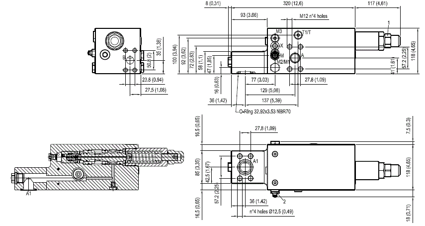
RE18309-17-dim(2023-10-26)