


In an assembly EDG block, the inlet section can be configured for either a fixed displacement pump or load-sense variable displacement pump. When simultaneous machine functions are actuated, the pre-compensators will automatically adjust to the highest load pressure via a shuttle arrangement, making the system circuit independent of variations in loads and pump pressures.
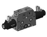
EDG-D-O...
![]() NEW spool position sensor available for this valve. See RE18300-30
NEW spool position sensor available for this valve. See RE18300-30
Main Field of Application
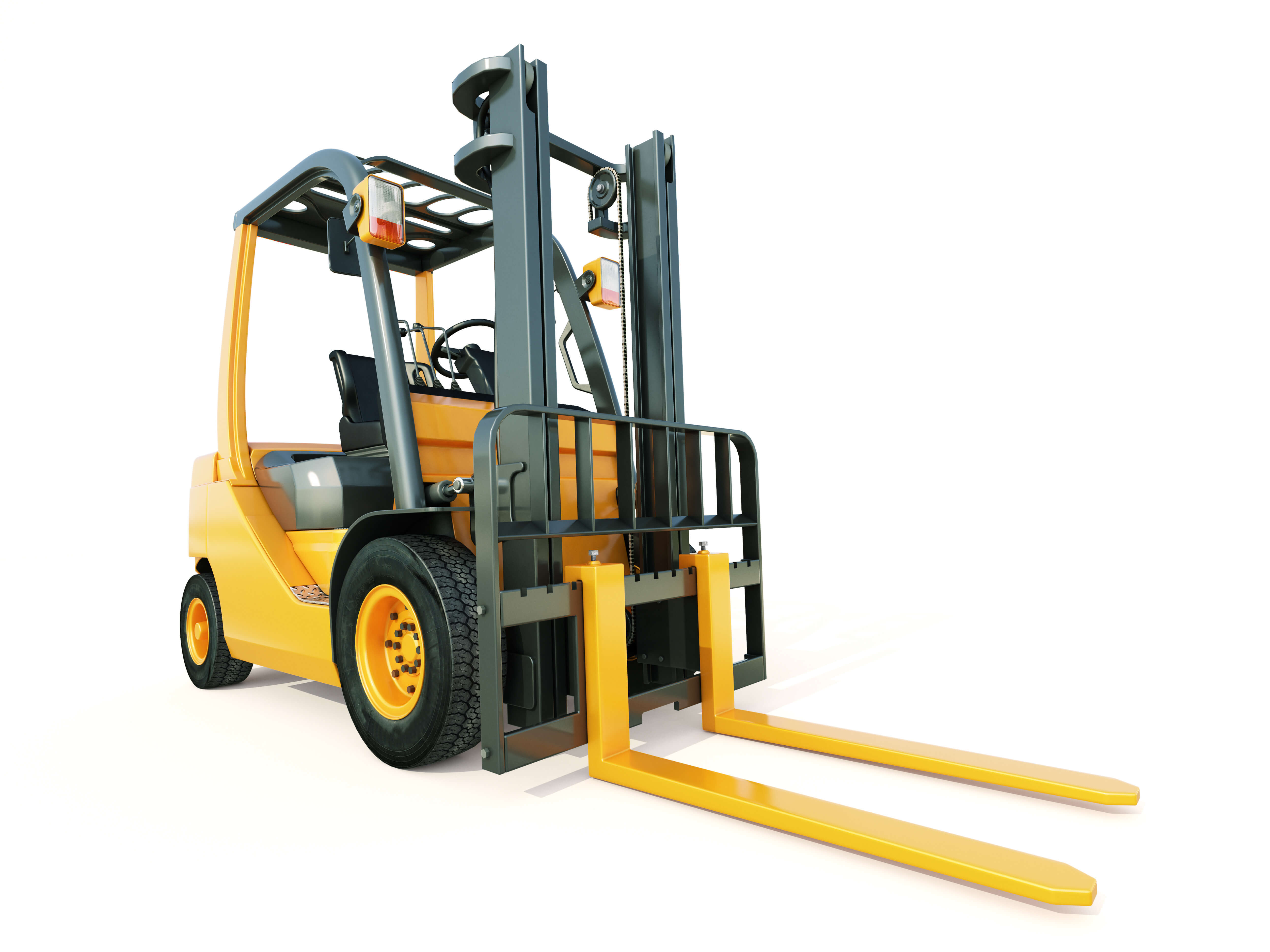
- Truck mounted applications
- Forestry machinery
- Forklifts and Telehandler
- Municipal vehicles
- Cranes
- Construction machines
- Aerial working platforms
- Heavy duty vehicles
- Agricultural machines
New Series 1 features:
- Label
- Flange with drain line for VMGLS and combination for EDG Electrohydraulic actuation
- Lever Manual override option
- Body valve zinc plating treatment for higher corrosion resistence protection up to 500h
Size:
- 1
Series:
- 6
Maximum operating pressure:
- 350 bar (5000 psi) Pump side
- 350 bar (5000 psi) Consumer side
Port connections:
- G 3/8 - G 1/2 - SAE6 - SAE8
Table 1
Notches dimension selection --> Flow Rate
Local compensator bias spring
4bar
6bar
1 *
3 l/min
5 l/min
2 *
6 l/min
8 l/min
3 *
9 l/min
11 l/min
4 *
13 l/min
14 l/min
6 *
18 l/min
23 l/min
9 *
24 l/min
31 l/min
M *
-
40 l/min
*Note: standard spool types (symmetrical):
1111 - 2222 - 3333 - 4444 - 6666 - 9999 - MMMM
Table 2
Spool size selection guide
P->A (corresponding A->T same size or "I" size)
Notch size
1
2
3
4
6
9
M
P->B(corresponding B->T same size or "l" size)
1
X
X
●
●
●
●
●
2
X
X
X
◊
●
●
●
3
●
X
X
X
◊
●
●
4
●
◊
X
X
X
◊
●
6
●
●
◊
X
X
X
◊
9
●
●
●
◊
X
X
X
M
●
●
●
●
◊
X
X
X = Standard spool flow rate configuration
◊ = Special spool flow rate configuration, contact factory
● = Not available
Table 3 Full relief valve configuration setting
0
9
8
Without valve cavity on both sides (not drilled)
With valve cavity plugged (Normally closed plug)
With anti-cavitation valve
A
B
C
D
E
F
G
H
I
J
K
50 bar
60 bar
70 bar
80 bar
90 bar
100 bar
110 bar
120 bar
130 bar
140 bar
150 bar
725 psi
870 psi
1015 psi
1160 psi
1305 psi
1450 psi
1595 psi
1740 psi
1885 psi
2030 psi
2175 psi
L
M
N
O
P
Q
R
S
T
U
V
X
160 bar
170 bar
180 bar
190 bar
200 bar
210 bar
220 bar
230 bar
240 bar
250 bar
270 bar
290 bar
2320 psi
2465 psi
2611 psi
2756 psi
2901 psi
3046 psi
3191 psi
3336 psi
3481 psi
3626 psi
3916 psi
4206 psi
For pressure higher than 290 bar (4206 psi), contact factory.
Table 4 LS relief valve configuration setting
Option selection
Description Standard
setting (bar)
0
without valve cavity
-
1
30-90 bar (Setting range)
70
2
80-140 bar (Setting range)
110
3
135-225 bar (Setting range)
180
4
210-310 bar (Setting range)
250
5
290-380 bar (Setting range)
300
9
Normally closed plug
R930082023
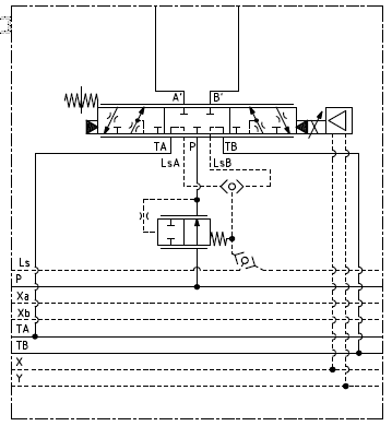
The EDG direct acting On-Off solenoid sectional valves with pressure compensation control the oil flow to actuators. These elements consist of a stackable housing (1) with a control spool (2), two solenoids (4), two return springs (3). Each solenoid (4), energized, displaces the control spool from its neutral-central position. When the spool is shifted, flow delivery starts and is controlled by a 2 way pressure compensator(7) (P > A; P > B).
When the solenoid is de-energized, the return spring pushes the spool back in its neutral-central position. Each coil (4) is fastened to the solenoid tube by the ring nut (5). A push-pin manual override is included to actuate the valve without electrical power as needed.
Load pressure compensation
The pressure compensator (7) keeps the pressure differential on the main spool (2). The flow to the consumers remains constant, despite varying loads.
The highest load pressure on the pump is signaled via the LS line and the integrated shuttle valve (6). Port relief valves with anti-cavitation function on A and B (9) protect the system against pressure peaks and cavitation. LS relief valves (8), for each consumer port, can be adjusted according to specific application requirements.
Code
Voltage [V]
Connector type
Coil description
Marking
Coil Mat no.
=OB 01
12 DC
EN 175301-803 (Ex. DIN 43650)
D3601 12DC
12 DC
R901393412
=OB 03
12 DC
AMP JUNIOR
D3603 12DC
12 DC
R901435507
=OB 04
12 DC
AMP JUNIOR Horizontal
D3604 12DC
12 DC
R901395031
=OB 07
12 DC
DEUTSCH DT 04-2P
D3607 12DC
12 DC
R901394397
=OC 01
24 DC
EN 175301-803 (Ex. DIN 43650)
D3601 24DC
24 DC
R901393577
=OC 03
24 DC
AMP JUNIOR
D3603 24DC
24 DC
R901435494
=OC 04
24 DC
AMP JUNIOR Horizontal
D3604 24DC
24 DC
R901395035
=OC 07
24 DC
DEUTSCH DT 04-2P
D3607 24DC
24 DC
R901394399
General
Valve element with 2 solenoids:
- 2.2 kg (4.85 lbs)
Valve element with 1 solenoid:
- 1.7 kg (3.75 lbs)
Fluid temperature:
- -30....+90 (-22....+194)
Hydraulic
Maximum pressure at P, A and B ports:
- 350 bar (5000 psi)
Maximum static pressure at T:
- 210 bar (3050 psi) [in case of Emergency Lever option, max. pressure is limited up to 30 bar at T]
Max. regulated flow at 6 bar (87 psi):
- 40 l/min (10.6 gpm)
For E schemes symmetrical spool pattern in neutral position (connection A
to T and B to T) E-schemes flow pattern with only meter IN (spool type E_ _ _ I
I)in neutral position: the opening area is approx the 50% of nominal
cross-section. This spool type is suitable in combination with load holding
valves applications.:
- Approx. 2% of the nominal cross-section
Hydraulic fluidGeneral properties: it must have physical lubricating and
chemical properties suitable for use in hydraulic systems.:
- Mineral oil based hydraulic fluids HL (DIN 51524 part 1). For use of environmentally acceptable fluids (vegetable or polyglycol base) please consult us.
Fluid Temperature:
- -30....+100 (-22....+212) (NBR seals)
Permissible degree of fluid contamination:
- ISO 4572: βₓ≥75 X=12...15 NAS 1638: class 9
Viscosity range:
- 20....380 mm²/s (optimal 30....46)
Electrical
Voltage type:
- DC
Voltage tolerance (nominal voltage):
- -10....+10%
Duty:
- Continuous, with ambient temperature ≤ 50° (122°F)
Coil wire temperature not to be exceeded:
- 180 °C (356 °F)
Insulation class:
- H
Compliance with:
- Low Voltage Directive LVD 73/23/EC (2006/95/EC), 2004/108/EC
Coil weight:
- 0.228 kg (0.503 lbs)
Voltage:
- 12 V
- 24 V
Power consumption:
- 20 W
- 20 W
Current (nominal at 20°C (68°F)):
- 1.04 A
- 0.54 A
Resistance (nominal at 20°C (68°F)):
 For applications with different specifications consult us
- 7.4 Ω
- 28.4 Ω
Performance limits
Measured with hydraulic fluid ISO-VG32 at 45° ±5 °C (113° ±9 °F); ambient temperature 20 °C (68 °F).
1
Ring nut for coil locking (Ø 30.3 mm).Torque 6 – 7 Nm (4.4 – 5.2 ft-lb).
2
Flange specifications. For tie rod and tightening torque information see data sheet RE 18301-90.
3
A and B ports.
4
Identification label.
5
Optional push-button manual override, EP type, for spool opening: it is pressure stuck to the ring nut for coil locking.Mat no. R930059524
6
Optional screw type manual override, EF type, for spool opening: it is screwed (torque 6-7 Nm (4.4-5.2 ft-lb)) to the tube as replacement of the coil ring nut. Mat no. R930059561.
1
Flow-boost system only for spool with nominal flow M. It always mounted on "a" side of the valve.
1
Order detail: HA Horizontal lever manual override option
2
Order detail: VA Vertical lever manual override option
3
Order detail: H1 Horizontal lever manual override option, 180° rotated
4
Order detail: V1 Vertical lever manual override option, 180° rotated
Not possible to switch from HA or VA to H1 or V1 and viceversa.