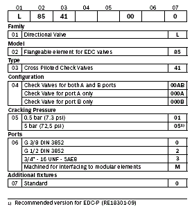


Description
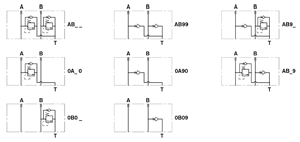
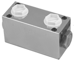
These secondary flangeable elements can be interfaced and bolted on top of the A and B ports of the ED elements of the directional valve assembly.
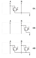
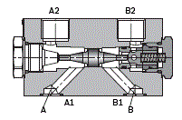
They incorporate two cross piloted check valve which allow free flow toward the A and B outlet ports, and lock in a leak free mode the flow returning from the actuator, until sufficient pilot pressure is built up in the opposite line and the check valve in opened.
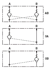
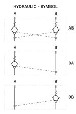
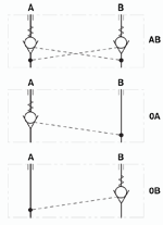
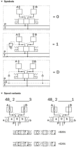
Depending on the version selected (AB, or 0A, or 0B), the PO check valve is in both A and B ports, or in A port only, or in B port only (see hydraulic symbols).
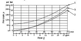
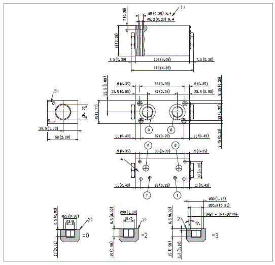
The pilot ratio in 3:1, consequently, the pilot pressure needs to be at least 1/3, or 33% of the load induced pressure in the actuator before Check Valve opens, and oil can return to tank. The body of these elements in made of Yellow Zinc Plated (Cr+3) Cast Iron (CI). Hydraulic Ports A2 and B2 are size G3/8 or G1/2 or ¾-16 UNF 2-B (SAE8).