Cartridge Valves - Pressure Control Valves - Pressure relief

VBL3-32

RE18319-12-01(2023-11-24)
Description

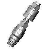
Flow is blocked from 1 to 2 until pressure increases to meet the selected valve setting, lifting the conical, pilot-stage poppet from its seat. This action exhausts oil above the main-stage poppet (low- leakage, seat type), allowing it to shift and provide relief flow through 2 to tank. Pressure at 2 is additive to the relief setting of the valve.

The anti-cavitation function makes up for lacking oil volumes caused, for example, by leakage when pressure valves respond or in the case of leading loads. If the pressure at main port 1 is lower than the one at main port 2, the spool will be lifted out of its seat. Hydraulic fluid flows from main port 2 to main port 1. Pressure shut-off function occurs by connecting pilot oil pressure to the external port 3 Pst, so the pilot oil is pressurized. This reduces the preload of the main spring and the maximum set system pressure.

¹) At 80% of pressure setting.

²) Torque value valid for installation in cast iron and steel manifolds. In case of different body materials, please consult factory.

General
Max. operating pressure port 1 (P):
  • 420 bar (6000 psi)
Max. pressure admitted port 2 (T):
  • 50 bar (725 psi)
Max pilot pressure port 3 Pst:
  • 30 bar (435 psi)
Max. flow:
  • 400 l/min (105.67 gpm)
Max. internal leakage¹):
  • 75 drops/min.
Fluid temperature range:
  • -20 to 120 °C (-4 to 248 °F) (Viton)
Installation torque²):
  • 150 Nm (110.36 ft-lbs)
Weight:
  • 0.75 kg (1.65 lbs) for FK
  • 0.86 kg (1.90 lbs) for LM
Special cavity:
  • FK - LM (see data sheet 18325-75)
Lines bodies and standard assemblies:
  • Please refer to section “Hydraulic integrated circuit” or consult factory
Seal kit (Viton):
  • Code: RG32R2040540100 for FK
  • material no: R930077563 for FK
  • Code: RGLMR2040540100 for LM
  • material no: R930078462 for LM
Fluids:
  • Mineral-based or synthetics with lubricating properties at viscosities of 10 to 380 mm²/s (cSt)
Recommended degree of fluid contamination:
  • Nominal value max. 10µm (NAS 9) / ISO 4406 20/18/15
Installation position:
  • No restrictions
MTTFD:
  • 150 years see RE 18350-51
Other Technical Data:
  • See data sheet 18350-50
Without surface protection:
  • In case of need of surface protection, please consult factory.
RE18319-12-02(2023-11-24)
RE18319-12-order(2023-11-24)
RE18319-12-dim(2023-11-24)
Type
A
B
C
L
F
D
E
M
Wrench size
SW4
SW5
Tightening torque [Nm (ft-lbs)]
SW1
SW2
SW3
SW1
SW2
SW4
FK
37
30
14
119
4
24
37
M33x1
34
19
36
36
27
150
15
10
(1.46)
(1.18)
(0.55)
(4.68)
(0.16)
(0.95)
(1.46)
(1.34)
(0.75)
(1.42)
(1.42)
(1.06)
(110.63)
(11)
(7.4)
LM
44
36
19
110.5
3.4
33
41
M36x1.5
36
19
36
36
27
150
15
10
(1.73)
(1.42)
(0.75)
(4.35)
(0.13)
(1.30)
(1.61)
(1.42)
(0.75)
(1.42)
(1.42)
(1.06)
(110.63)
(11)
(7.4)