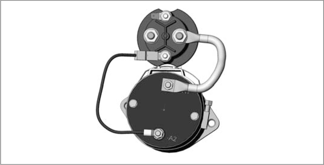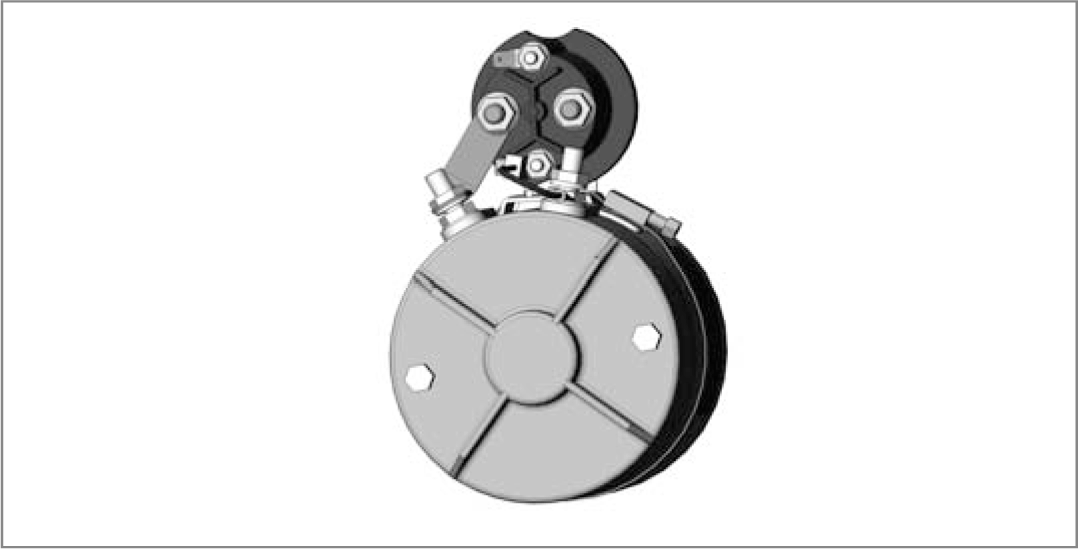
Compact Power Modules - ME-MR Series

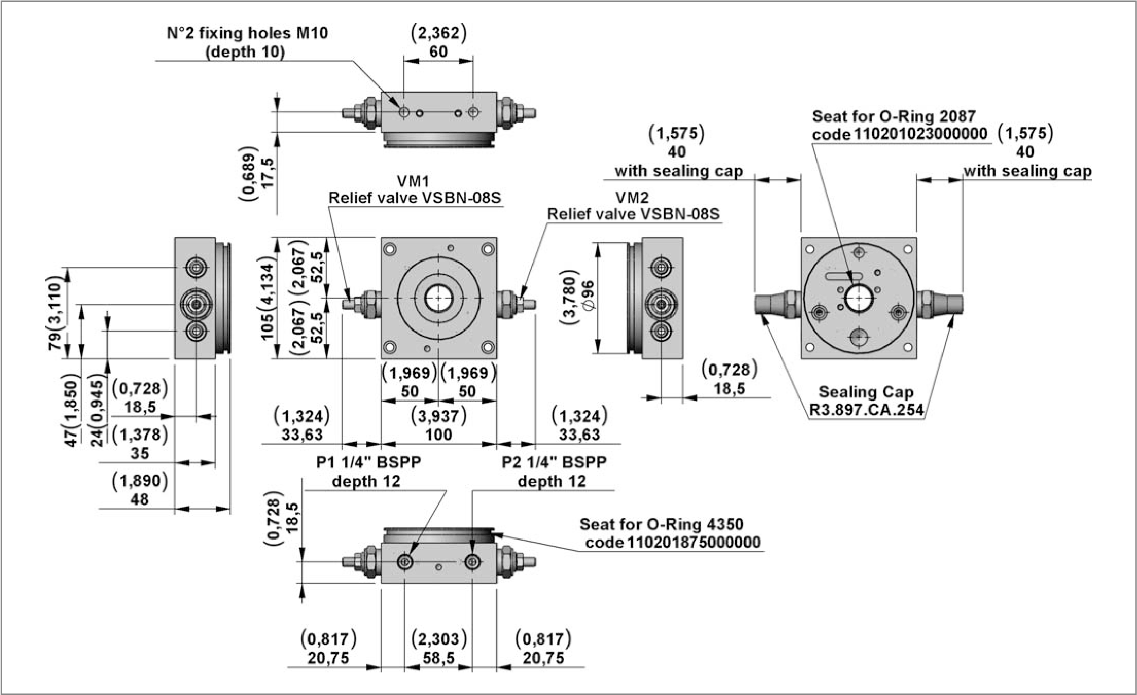
ME-MR

Compact power modules ME – MR Series
RE18306-01-1

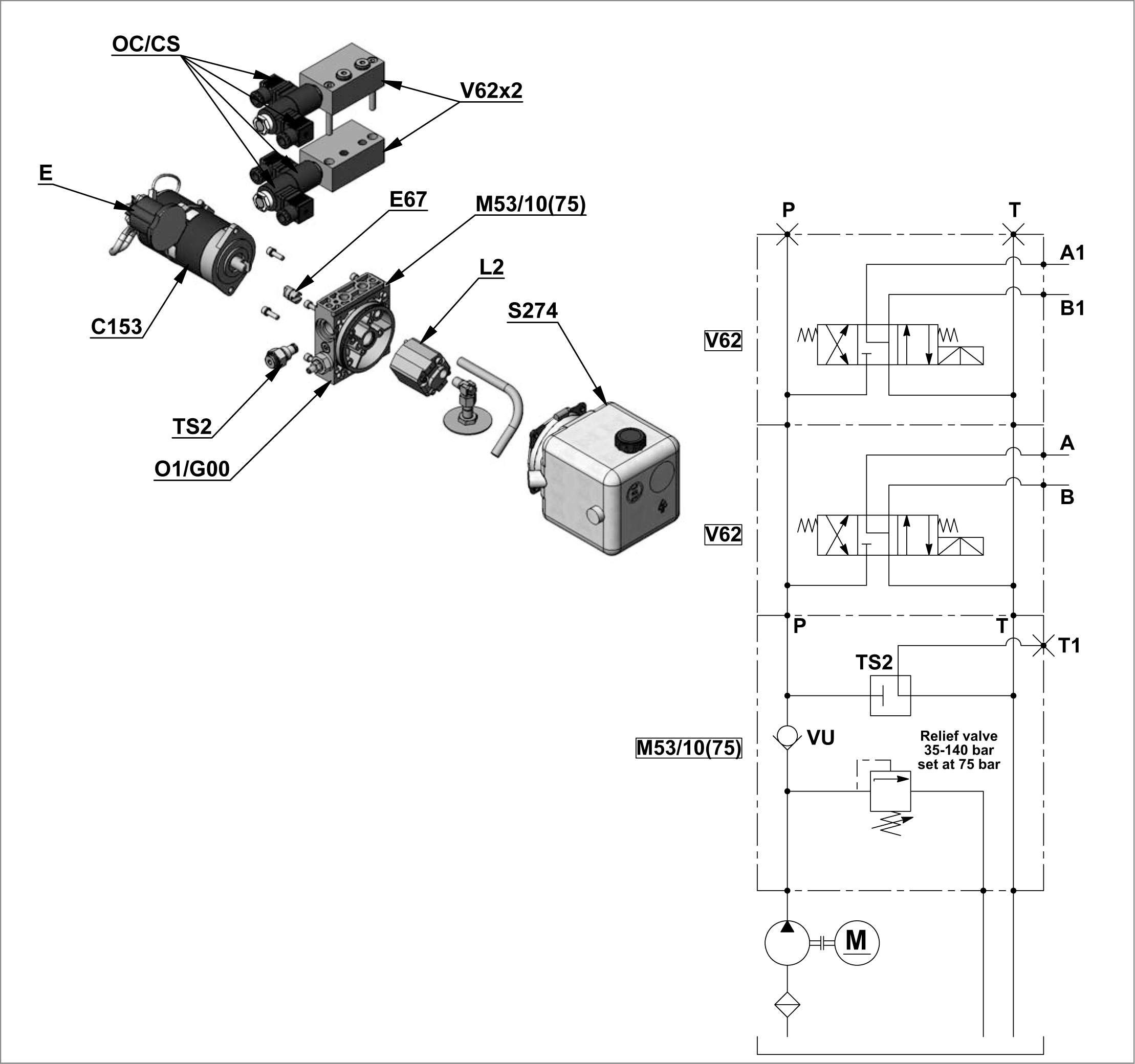
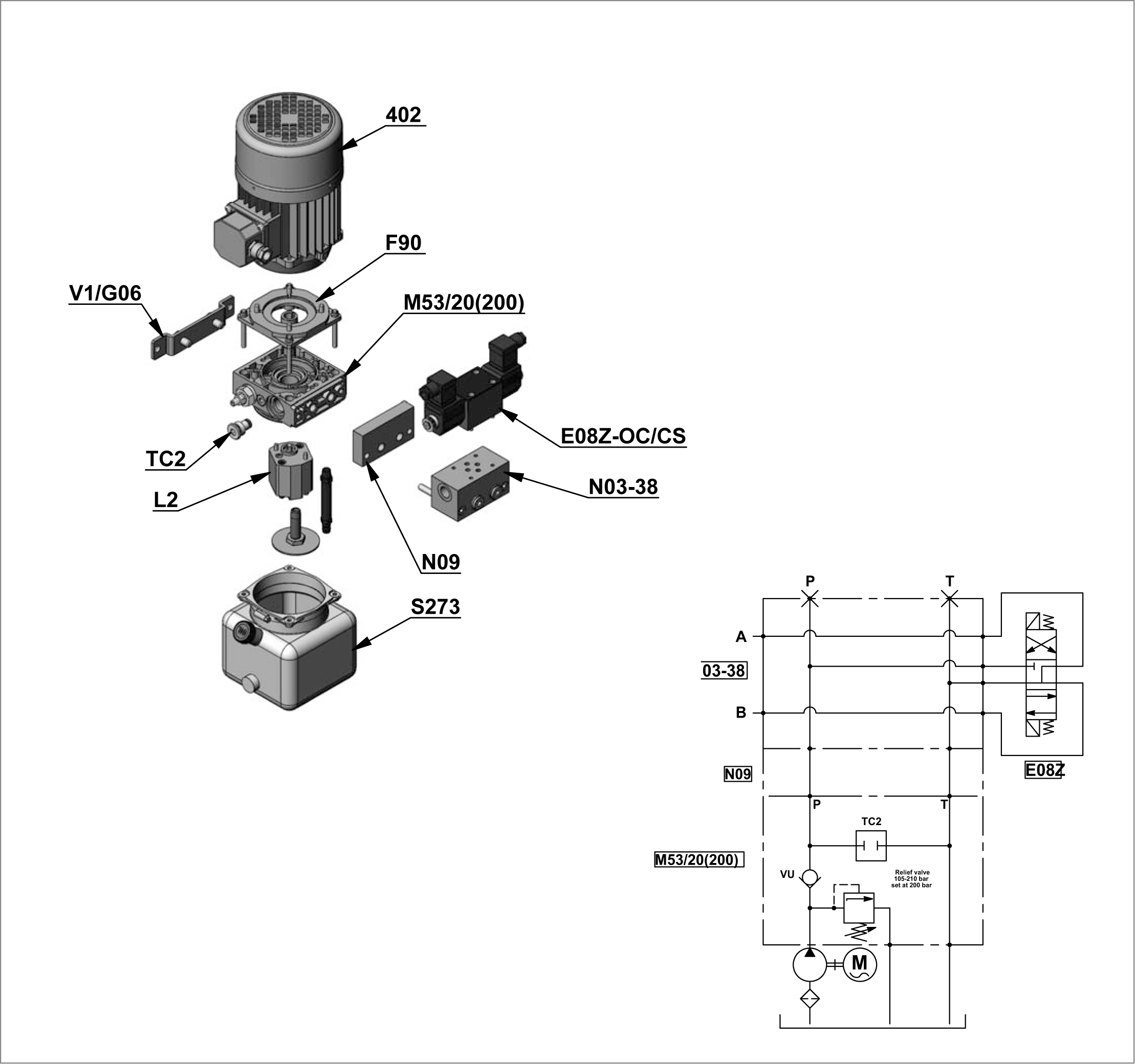
Example of Ordering Details for Compact Power Modules ME with A.C. Motor
RE18306-01-2

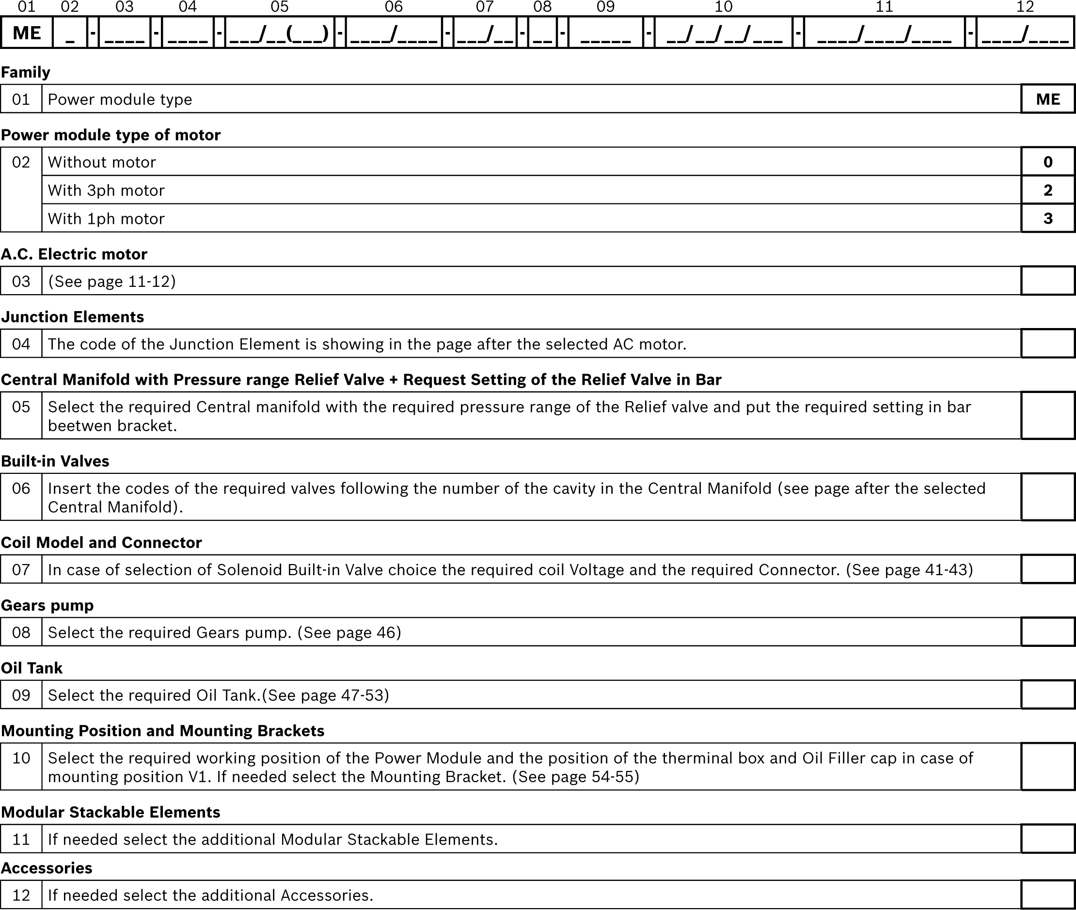
Ordering Details for Compact Power Modules with AC Motor

RE18306-01-3
RE18306-01-4

Example of Ordering Details for Compact Power Modules ME with D.C. Motor
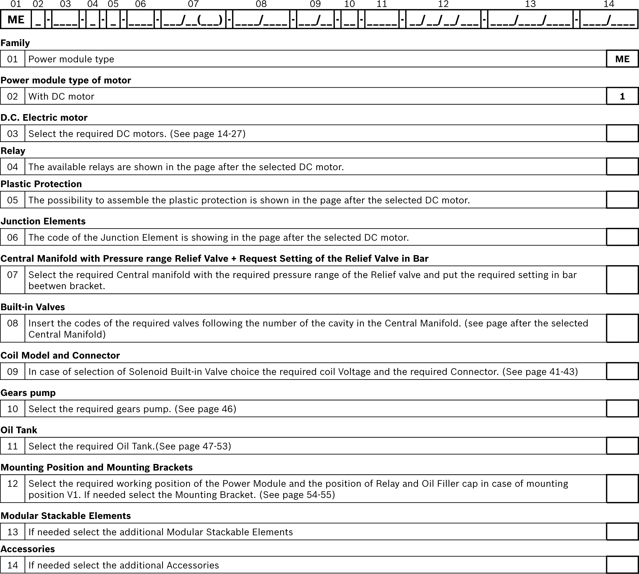
RE18306-01-5

Ordering Details for Compact Power Modules with AC Motor

RE18306-01-6
RE18306-01-7

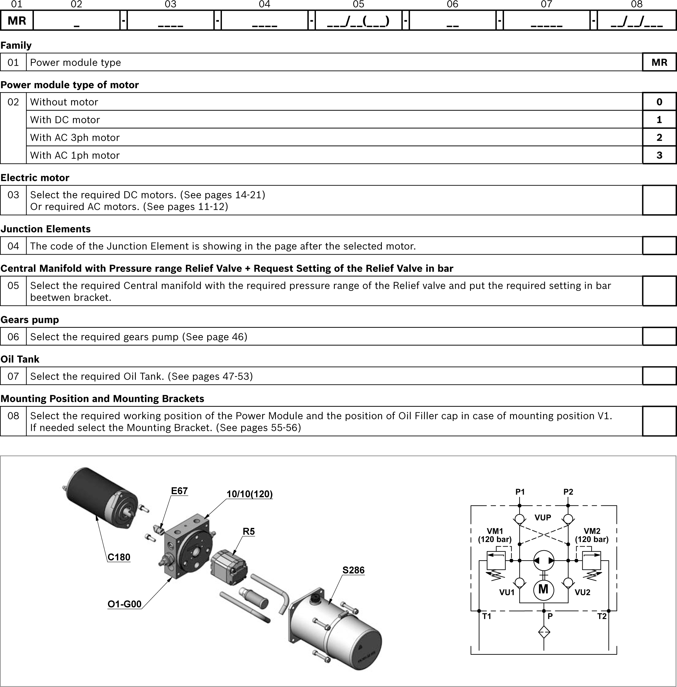
Ordering Details for Compact Power Modules MR

RE18306-01-8

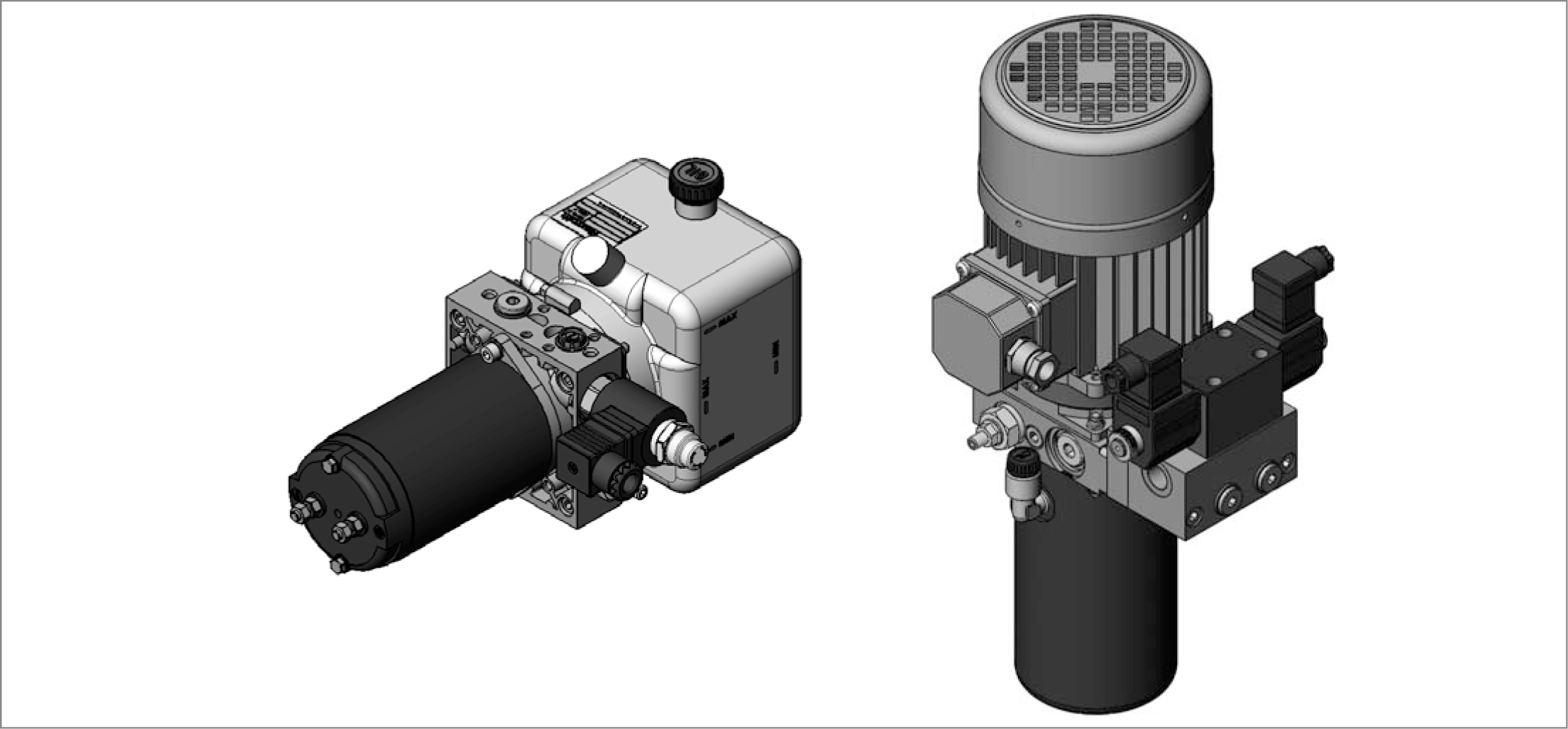
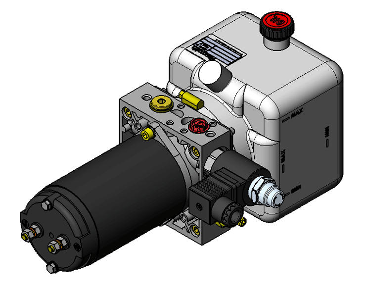
Through the years DCOC has developed a highly evolved modular system resulting in powerful, flexible and cost effective power pack range, identified as “compact power modules”. In its easier configuration, a “compact power module” is an assembly of electric motor, central manifold with valves, pump, oil tank and a few connection elements. The central manifold, with its built-in valves, allows to achieve a large variety of hydraulic control circuits. If more complex circuits are needed, modular integrated blocks can be added by flange mounting, or interfacing, to the central manifold to extend its capabilities.


Typical applications

Passenger lift

Fork lift

Car and motorcycle lift

Lift table

Dumper

Tail gate

Scissor lift

Gangway and davits for boats

Material handling

Foods machinery


Power module selection

Choose the circuit which meets your application requirements.

Take note of all dimensions resulting from the basic components chosen for your application.

NOTE: Dimensions may vary slightly and should be confirmed by DCOC, if the assembly is to be installed in a space with narrow clearance.

The tank capacity and the tank dimensions need to be large enough to assure proper pump suction: there must always be a reserve of oil in the tank when all cylinders are fully extended and avoid overflow when cylinders are fully retracted.

The tank must be evaluated also for best separation of air from oil, and for settling down oil contamination. It should be placed in a space with, at least, natural ventilation and it should permit enough heat dissipation to prevent high fluid temperature.

Select the electric motor by evaluating the power needed and the motor compliance with the heat developed during the expected run time (or “duty cycle”).


Hydraulic fluid for compact power module

Mineral oil based hydraulic fluids suitable for hydraulic systems can be used; they should have physical lubricating and chemical properties as specified by:

MINERAL OIL BASED HYDRAULIC FLUIDS HL (DIN 51524 part 1)

MINERAL OIL BASED HYDRAULIC FLUIDS HL P (DIN 51524 part 2)

For use of environmentally friendly fluids please consult DCOC.


Fluid viscosity, temperature range of the operating fluid, ambient temperature

The fluid viscosity should remain within the range 10 to 300 cSt (centistokes); recommended 15 to 120 cSt.

Permissive cold start viscosity is maximum 2000 cSt.

The fluid temperature should remain within the range -15°C and 80°C (5°F and 176°F).

Note: For compact power module with plastic tank the fluid temperature should remain within the range -15°C and 70°C (5°F and 158°F). Ambient temperature -15°C +40°C (5°F and 104°F).


Fluid cleanliness requirements and maintenance

We recommend a cleanliness of the operating fluid according to ISO 4406 Class 20/18/15 or cleaner.

All components of the hydraulic circuit , including hoses and actuators, must be flushed and cleaned before assembling, because the compact power module has a suction filter only.

The hydraulic fluid should be replaced after the first 50 hours, and then every 1000 hours, or, at least, once a year.


Power module installation

The mounting position (is basically un-restricted; just avoid installations that could compromise the pump suction, it is recommended to support the power module on vibration dampening blocks when the mounting structure is expected to vibrate.


Wiring and starting-up

The wiring between battery and electric motor should be selected in order to avoid excessive voltage drop (recommended less than 1 V).

It is strictly forbidden to allow the backwards rotation of the pump even at the first starting: to prevent reverse rotation, the wiring polarities must be correctly connected (except for the reversible pumps).

NOTE: when energized, the surface temperature of the electric motor could reach temperature levels of 60-80°C (140-176°F): care should be taken to avoid any accidental contact of people with the motor surface.


A.C. motors

The tolerances on the nominal voltage are:

Single phase motor: 230V +/-5% -

Three phase motor: 230-400V +/-10%.

Protection degree: IP54 (protection against dust and water splash).

Insulation class: F (155°C) (311°F).

All motors are aluminum alloy die cast without painting.


D.C. Motors

DCOC has a wide range of D.C. motors. In the following pages you will find a selection of our standard range.

For further information about our complete range please contact our Sales department.

Some motors Ø80 have reversible rotation (see the table) and are suitable for application in CPM MR series.

All the others motors shown have clockwise rotation suitable for driving our counter clockwise gear pumps.

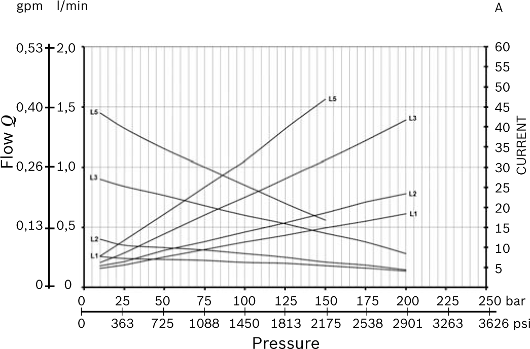
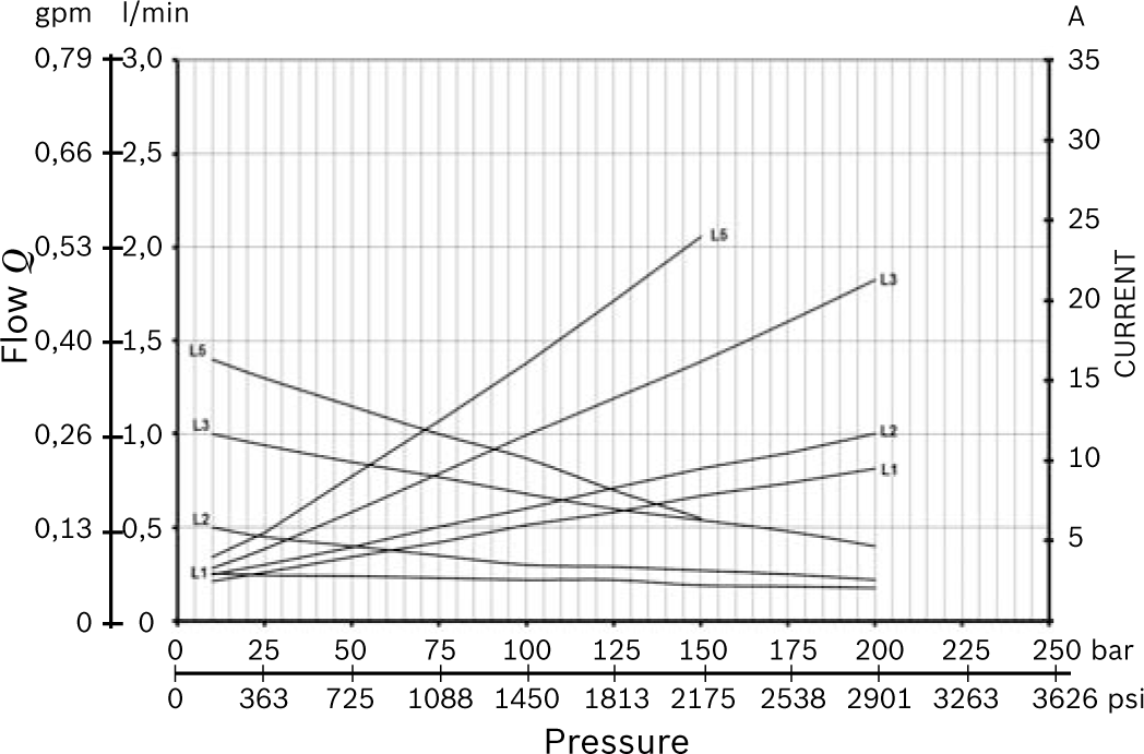
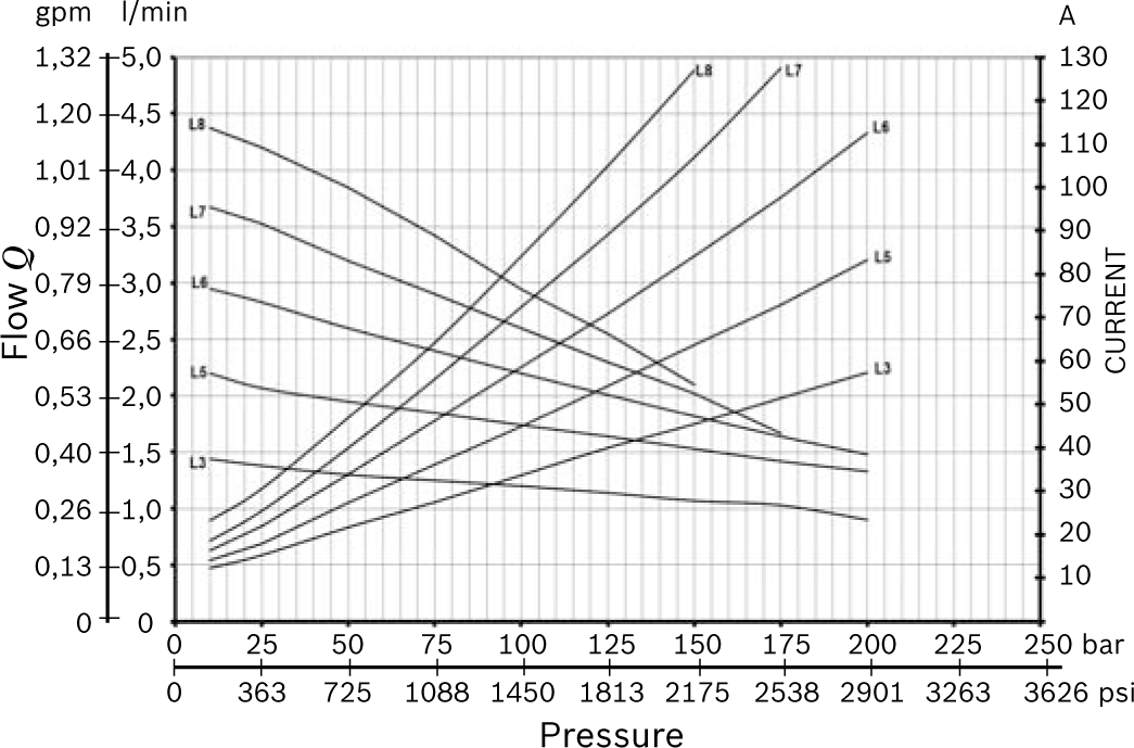
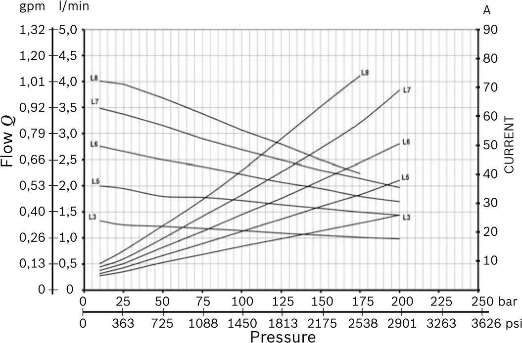
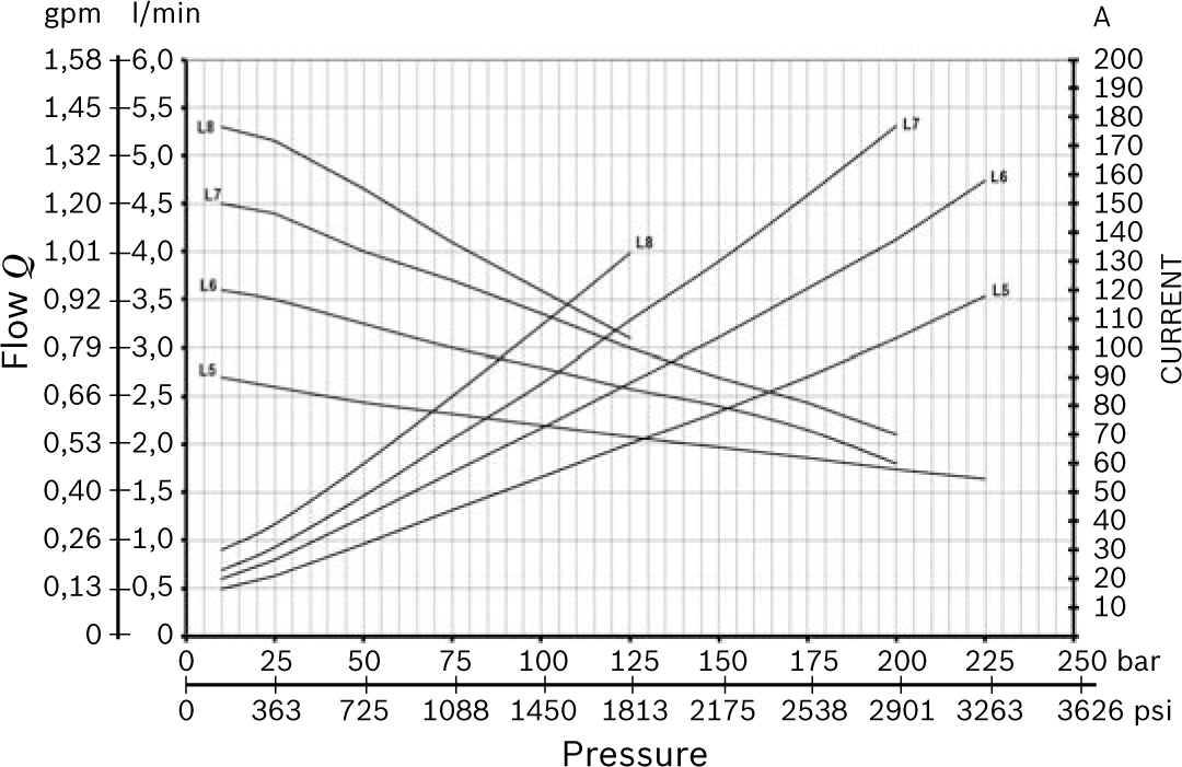
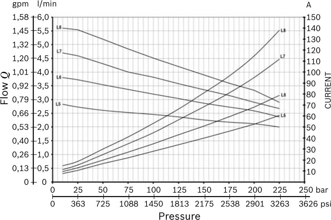
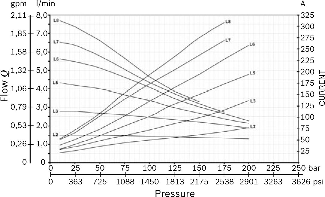
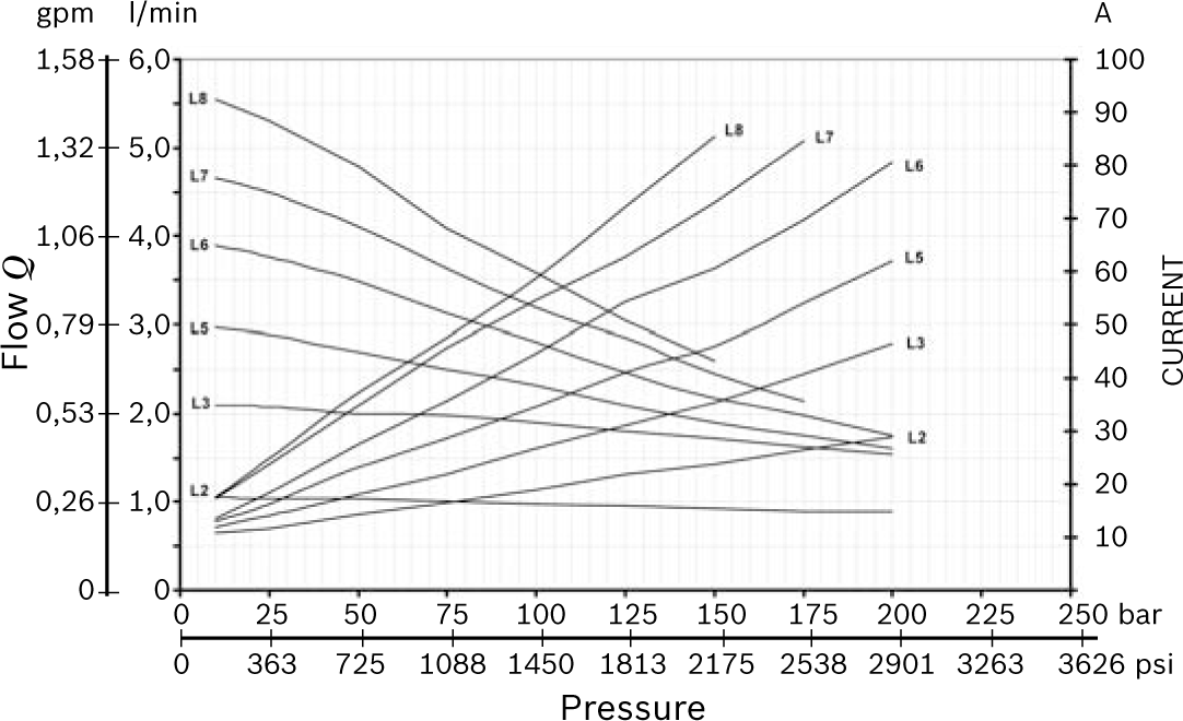
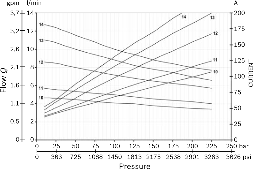
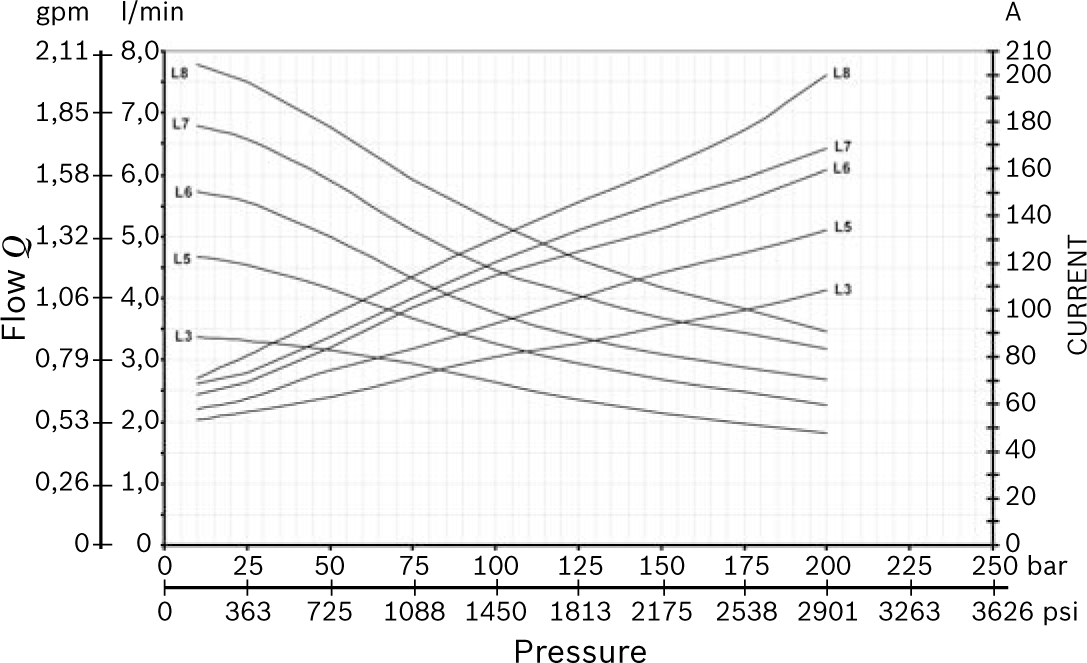
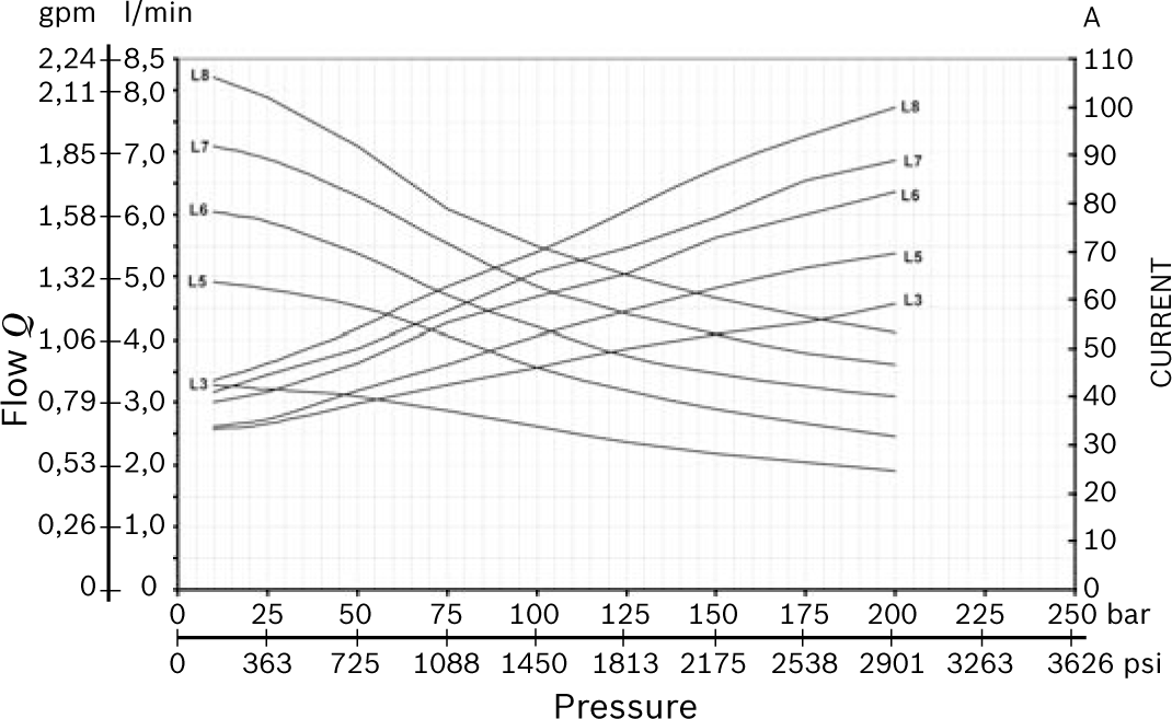
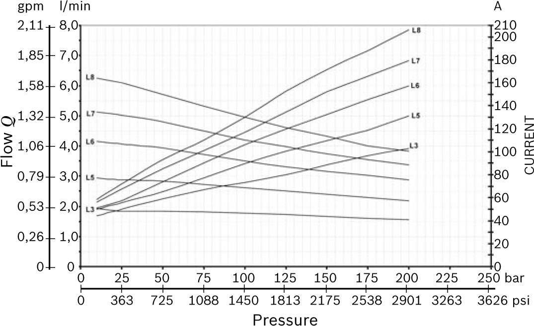
For each motor a diagram is shown that enables the customer to select the right pump displacement needed for the required flow and working pressure.

To be sure of selecting the best electric motor for the application, also the duty cycle has to be verified.

Following are the definitions of the type of duty cycles:

S2 = Short time duty cycle: indicate the number of minutes the motor can operate before reaching the maximum allowable temperature. After this time the motor must cool down until the ambient temperature is reached.

S3 = Intermittent duty cycle: indicate the maximum time percentage (%) based on 10 minute period within the motor can run until reaching the maximum allowable temperature. For example an S3 value of 15% = 1,5 minutes running time every 10 minutes period. For 8,5 minutes the motor is switched-off.

The S2 and S3 values are related to the current draw. On the label of motor are indicated the S2 and S3 values referred to the nominal power of the motor.

To check the S2 or S3 value at different conditions is necessary to find the value of current in the motor-pumps diagram and related it with the represented list.

All the diagrams motor-pumps are obtained at the nominal voltage of 12 or 24 Volt using fluid ISO VG 46 at 20-30°C (68-86°F).


Central manifolds

All the Central Manifolds shown in the catalogue are made in die cast aluminium alloy except the manifold code 10 for CPM MR series that is made by extruded bar. The validation of the Central Manifolds follows a life-test with 250 bar (625 psi) pulsed pressure repeated for 300.000 cycles.


Built-in valves

A wide range of cartridge valves and special plugs is available to be assembled in our Central Manifolds. The cartridge valves shown are designed for use in our Compact Power Module and are manufactured using steel with high mechanical strength. Surface treatments protect the exposed parts to the external environment. Standard seals are NBR (BUNA-N) with backup rings in PTFE. The cartridge valves with “leak proof seat design” have an average leakage of 10-15 drops/minute (< 1 cm3/minute 0.06 in3/min.) at the maximum pressure using fluid ISO VG46 at 40°C (104°F).

The validation of the cartridge valves follows a life-test at pulsed maximum pressure (indicated for each valve) repeated for 500.000 cycles.

All the solenoid cartridge valves are fitted with protective

O-Rings installed between the pole tube and the coil. These O-Rings protect the internal parts from condensation and contaminants, which could cause malfunction.

All the solenoid cartridge valves are designed for operating in D.C..

Power supply in A.C. requires a connector with bridge rectifier included.


External gear pumps

DCOC offers a wide range of External Gear Pumps to cover different kind of applications. The standard version are suitable for the biggest part of applications. All the pumps are pressure compensated to guarantee the best efficiency.


Oil tanks

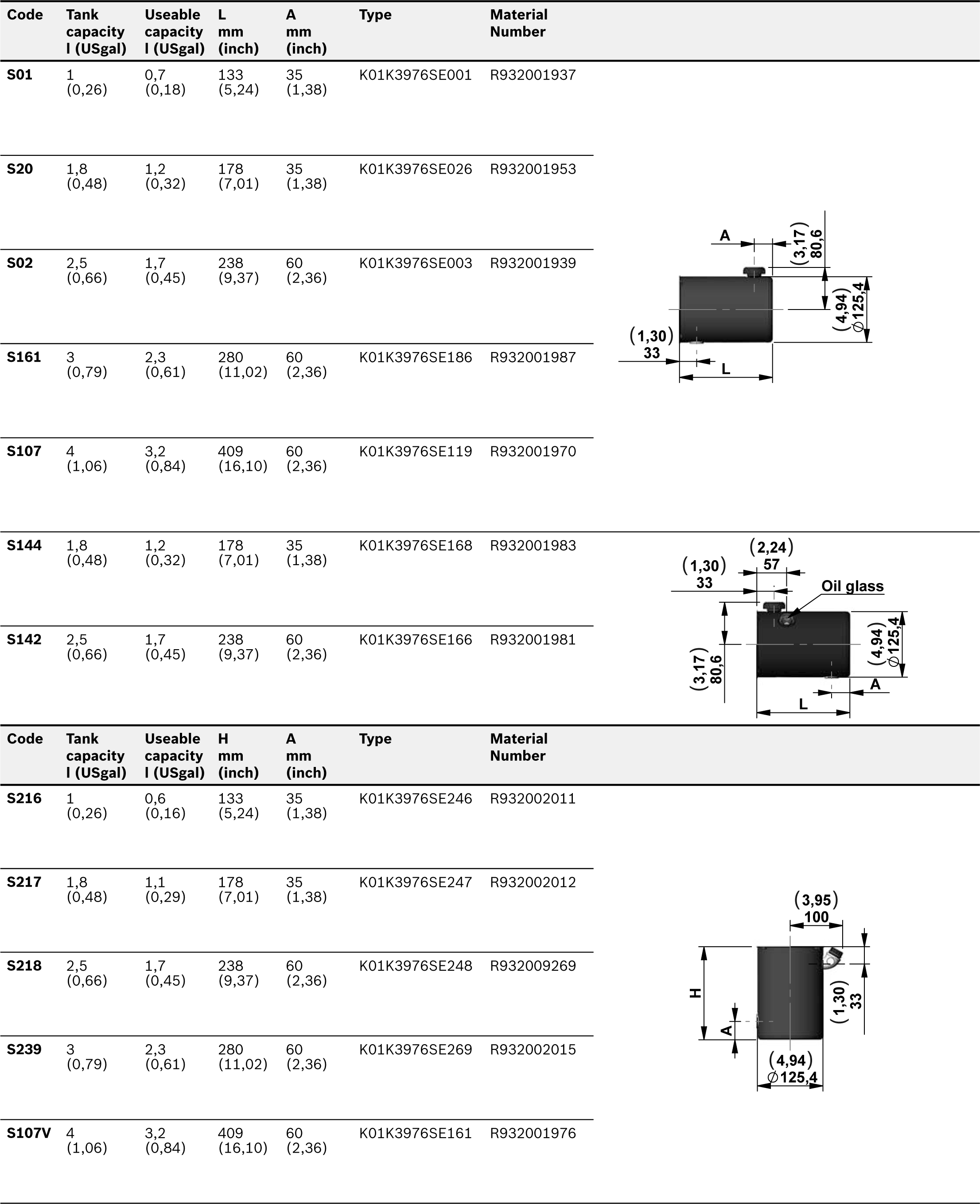
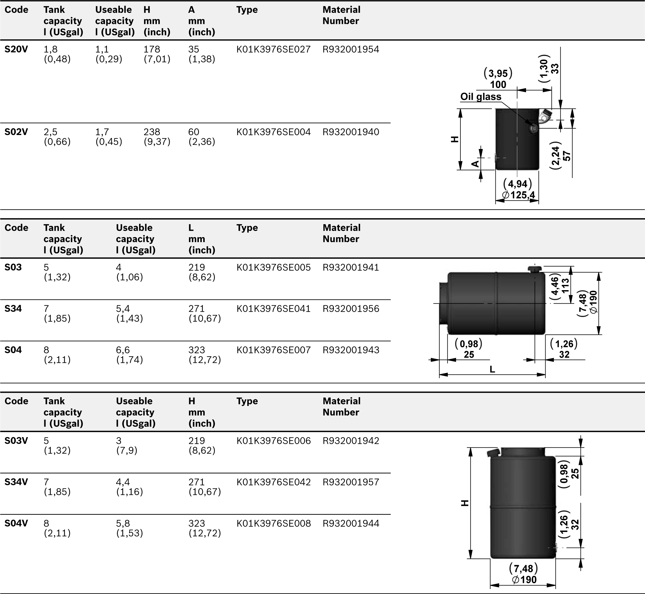
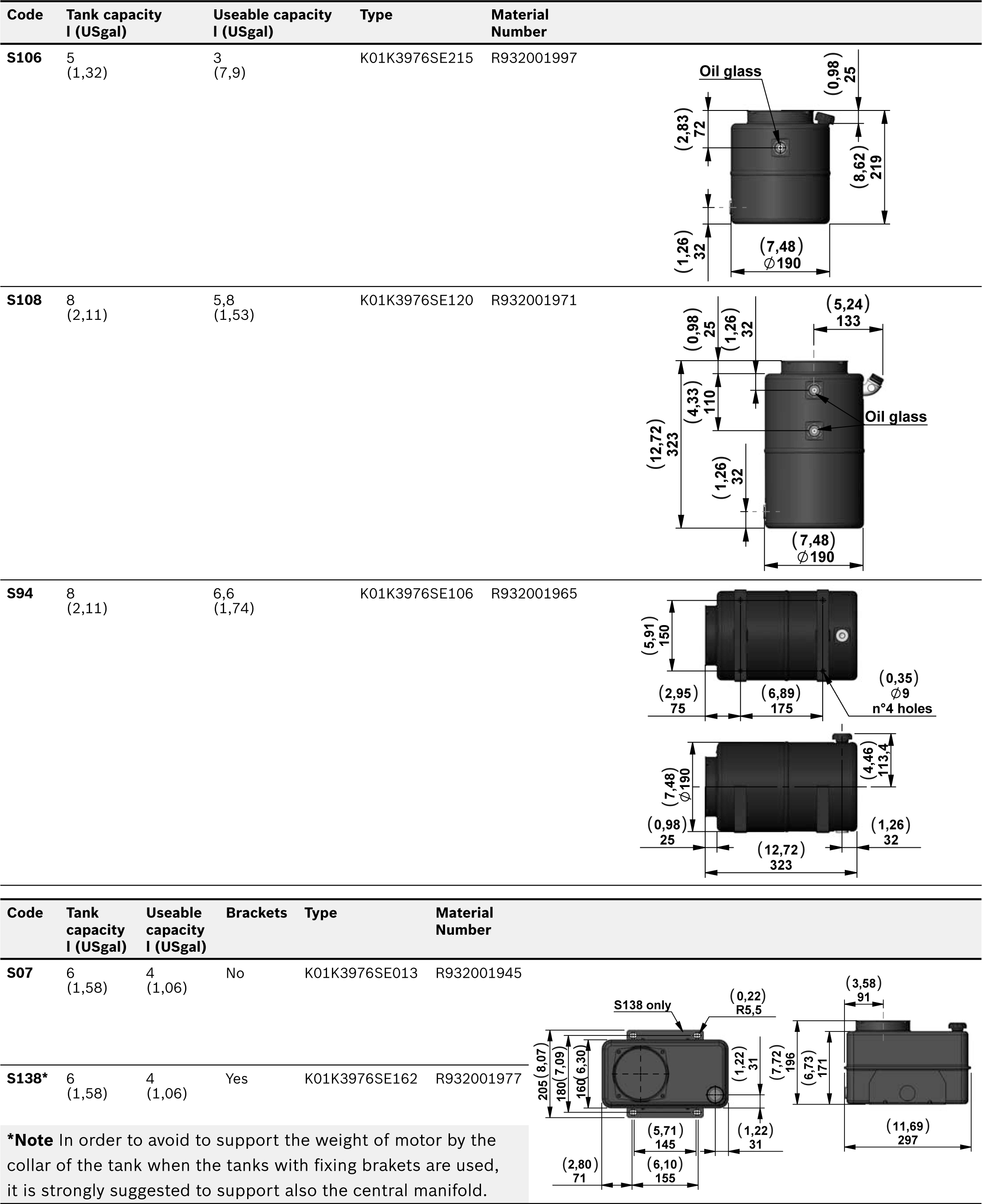
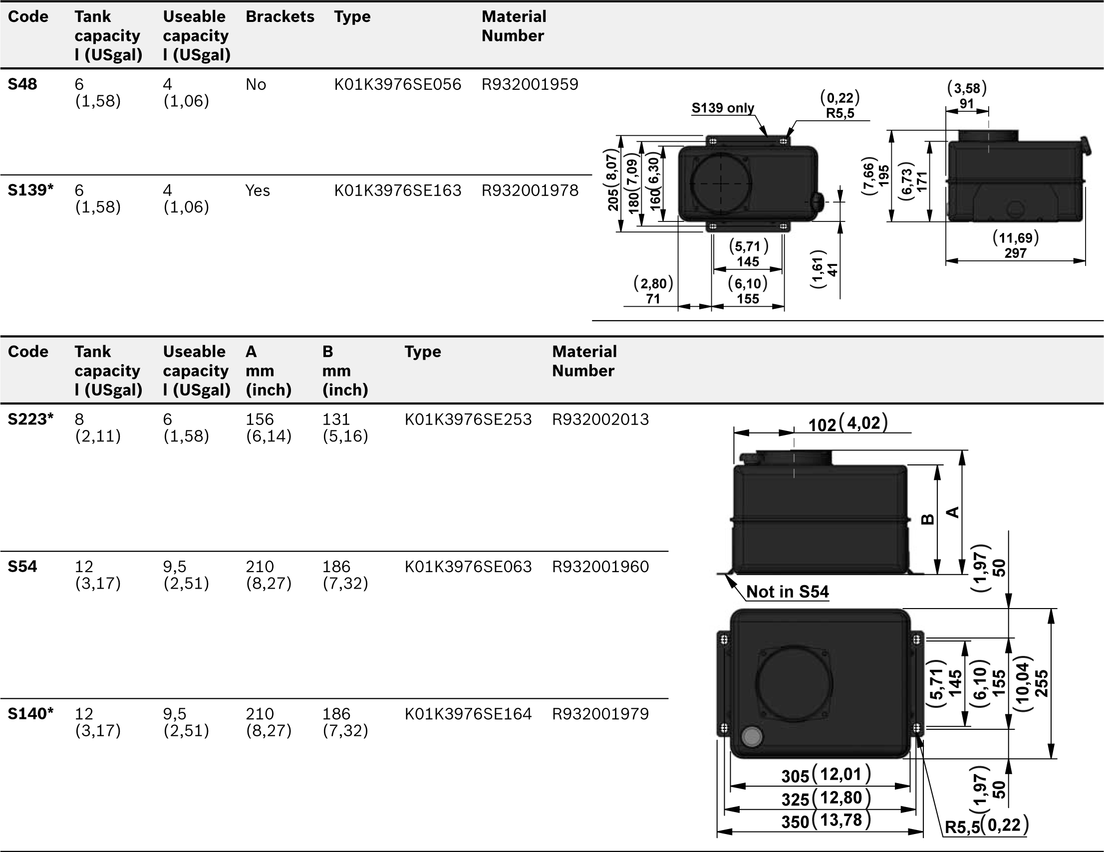
In this catalogue you will find a wide selection of steel and plastic tanks available as a standard product. If a special tank is required please contact our Sales Department. Steel tanks have Black paint finish and are suitable for operating temperature range -15°C / +80°C (5°F / 176°F). Plastic tanks are obtained in one piece in order to avoid welded parts that are weak points at extreme temperature and vibrations. Plastic tanks are suitable for operating temperature range -15°C / +70°C (5°F / 158°F).

NOTE: even if the plastic tank mounting system is designed to avoid oil leakage the tank must be securely anchored when fitted in mobile equipment and when subject to shocks and heavy vibrations. Please check that the anchorages do not stress or deform the tank.


Modular stackable elements

Our modular system offers a wide range of standardised elements. They are divided in two main series:

Modular Elements “N” series: Modular blocks for different mounting position with mechanical valve or interface for CETOP valves to create parallel or series circuits.

Modular Elements “V” series: Modular blocks that incorporate solenoid operated cartridge valves 2,3,4 way. All the Modular Elements are made in extruded aluminum alloy.

In the catalogue you will find a selection of the main used models.

Note: To reduce the complexity of the system and optimize the available space, special Modular Elements can be designed and manufactured following the customers needs. In this case please contact our Sales Department.


European machine directive 2006/42/CE

According to the Machine Directive2006/42/CE, a complete power module, as described in paragraph 15 and made available to the European market, enters into the definition of “partly completed machinery”.

Instead, the power module sub-assemblies (motor, pump, reservoir, central manifold,...), when not assembled into a complete power pack, are considered “components” which can be employed in a “machinery” or a “partly completed machinery”. In this case, the DCOC components and sub- assemblies must be fitted in compliance with all the relevant technical data sheet applicable to the product, and shall not be operated, adjusted or disassembled before the complete machinery where they are incorporated has been declared to be in compliance with the Machine Directive 2006/42/CE.

NOTE: All the components shown in the catalogue ARE NOT


Technical information

Below you will find the most common equations used in hydraulics:

 
Common Units
Symbols
Equations
Flow
l/min
Q
Q= D×n 1000 ×0.95
Operating pressure
bar
P
P= F 0.1×A
Internal diameter hydraulic cylinder
mm
d
Area of hydraulic cylinder
mm2
A
A= π× d 2 4
Piston force
N
F
Drive shaft
rev/min
n
Power requirement for motor
kW
N
N= P×Q 612
Pump displacement
cm3/rev
D
Torque requirement
Nm
M
M= D×P 62.8×0.87

ME

RE18306-01-14

Smallest overall dimensions.

DC motors up to 2200 W (2,95 hp).

AC motors up to 1100 W (1,48 hp).

Pump displacement up to 1,5 cm3 (0,09 inch3).

Pressure up to 230 bar (3336 psi).


Reversible Type MR series
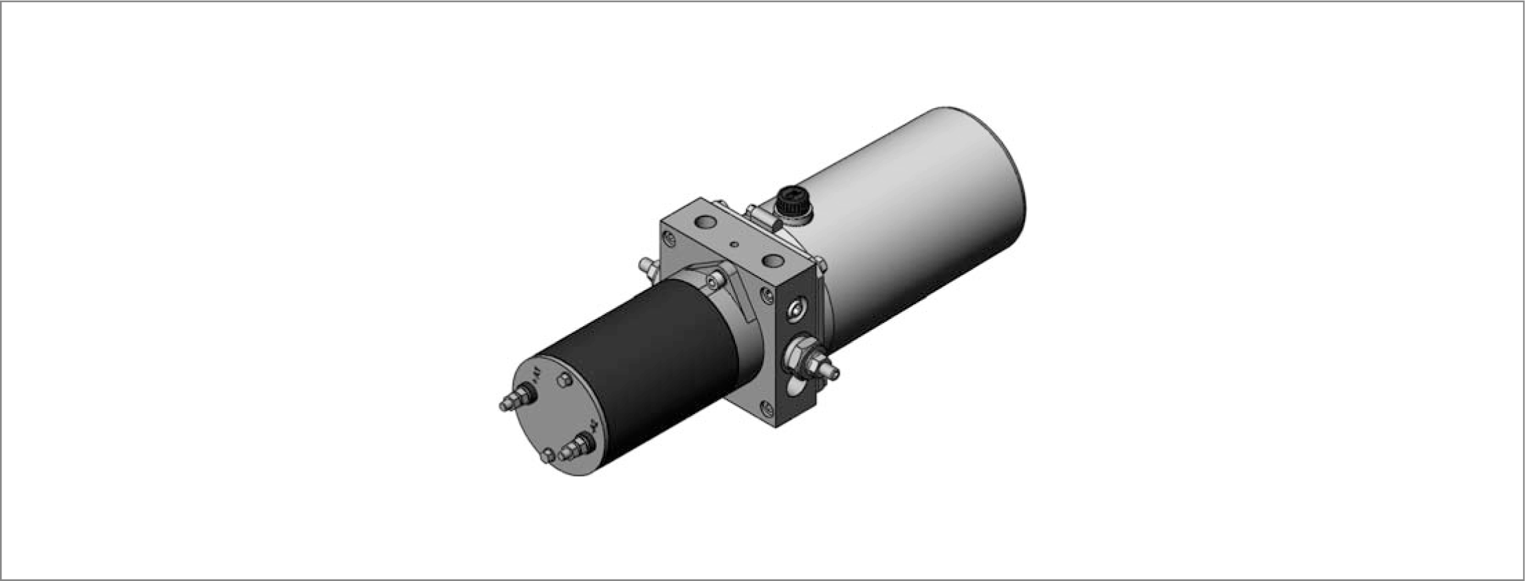
RE18306-01-15

Smallest overall dimensions.

DC motors up to 800 W (1,1 hp).

AC motors up to 370 W (0,5 hp).

Pump displacement up to 1,5 cm3 (0,09 inch3).

Pressure up to 190 bar (2756 psi).


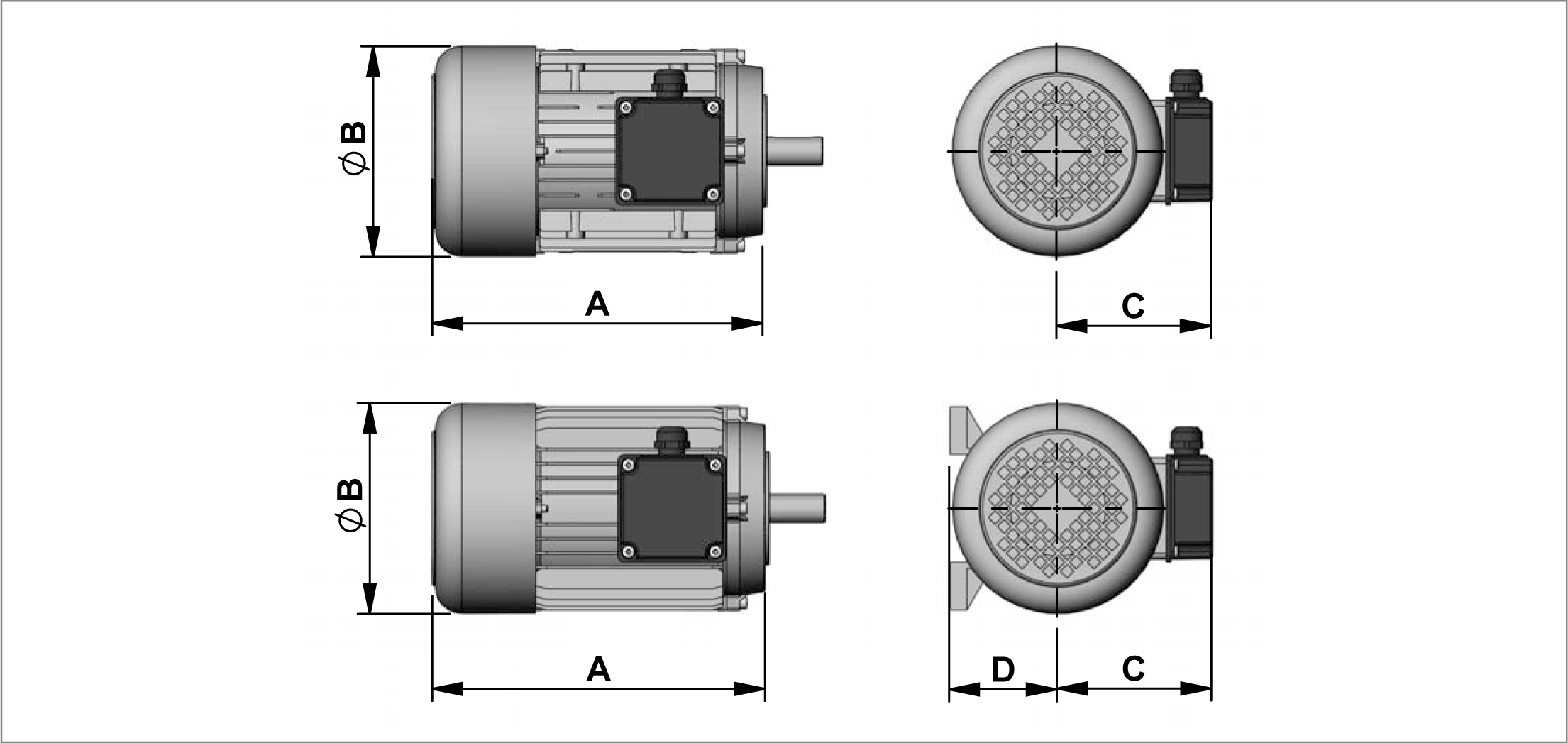
Standard A.C. Motors in B14 form.

RE18306-01-16

4 Poles Three Phase

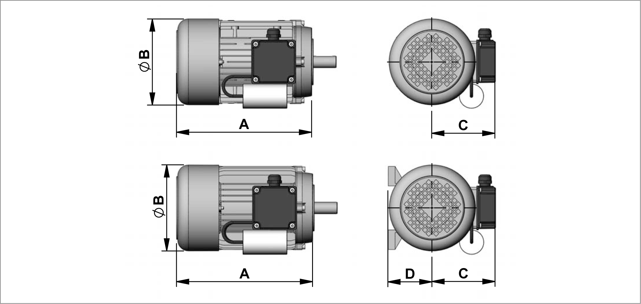
Current Motors 230/400V 50Hz 278-/480V 60Hz Form B14 Protection IP54 (1450 rpm at 50Hz)

Code
Type
Material Number
Power [kW]
Power [hp]
Size IEC
Duty Cycle
Amm (inch)
ØBmm (inch)
Cmm (inch)
Dmm
Efficiency Classe
402
C1622670DR
R932008027
0,25
0,35
71
S3=60%
218(8,58)
140(5,51)
109(4,29)
71(2,79)
IE1
403
C1622680DR
R932006105
0,37
0,5
71
S3=60%
212
140
113
71
IE1


(8,35)
(5,51)
(4,45)
(2,79)
 
404
C1622150DR
R932006106
0,55
0,75
80
S3=60%
250
156
125
80
IE1


(9,84)
(6,14)
(4,92)
(3,15)
 
405
C1622160DR
R932006107
0,75
1
80
S2
250
156
125
80
IE1


60MIN.
(9,84)
(6,14)
(4,92)
(3,15)
 

Standard A.C. Motors in B14 form.

RE18306-01-17

On request motors in B34 form are avaible. In this cases, please put “B34” after the code of the motor when filling in the description. Example “408MB34”.


4 Poles Single Phase

Current Motors 230V 50Hz Form B14 Protection IP54 (1450 rpm at 50Hz)

Code
Type
Material Number
Power [kW]
Power [hp]
Size IEC
Duty Cycle
Amm (inch)
ØBmm (inch)
Cmm (inch)
Dmm (inch)
402M
C162271000
R932000496
0,25
0,35
71
S1
218 (8,58)
140 (5,51)
109 (4,29)
71 (2,80)
403M
C162272000
R932000497
0,37
0,5
71
S1
212 (8,35)
140 (5,51)
113 (4,45)
71 (2,80)
404M
C162239000
R932000471
0,55
0,75
80
S1
250 (9,84)
156 (6,14)
125 (4,92)
80 (3,15)
405M
C162240000
R932000472
0,75
1
80
S1
250 (9,84)
156 (6,14)
125 (4,92)
80 (3,15)

NOTE: The electric motors with standard flange shown in this pages are delivered by different certified suppliers. This means the indicated dimensions could change a little, depending on which manufacturer will be assembled. On the CPM the choice of the manufacturer is based on our stock availability.


Junction Elements for A.C. Electric Motor Standard Flange
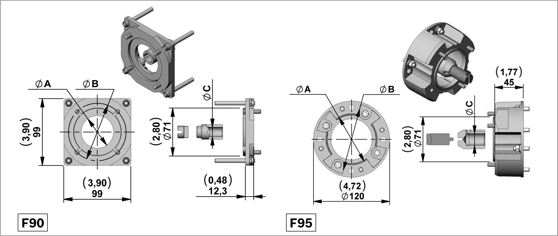
RE18306-01-18

Junction Elements for manifolds ME - MR series (STD COUPLINGS)

Code
Motor Codes
Size IEC
Amm (inch)
Bmm (inch)
Cmm (inch)
Hmm (inch)
Type
Material Number
F90
402-403-402M-403M
71
70 (2,76)
85 (3,35)
14 (0,55)
12,5 (0,49)
K01X3970TR099
R932002070
F95
404-405404M-405M
80
80 (3,15)
100 (3,94)
19 (0,75)
-
K01X3970TR100
R932002071

NOTE: The junction element F95 is not usable with manifold MR serie.

RE18306-01-19
Code
Voltage [V]
Power [W]
Duty Cycle S3% S2 min.
Thermal Switch
ULCertified
Protection index
Direction of rotation
Type
Material Number
C177
12
150
10% 2,5min
NO
YES
IP 54
<->
C1620S1077M
R930056881
C178
24
150
10% 2,5min
NO
YES
IP 54
<->
C1620S1078M
R930056882

Electric Motor C177 (12V – 150W) Diagrams

RE18306-01-20

S2 - S3 performance

Amps
S2 (min.)
S3(%) (10 min.)
20
8
20%
30
4
8%
50
1,5
3%

Electric Motor C178 (24V – 150W) Diagrams

RE18306-01-21

S2 - S3 performance

Amps
S2 (min.)
S3(%) (10 min.)
10
4
10%
20
1,5
3%

NOTE: The values of the curves may change slightly depending on the brand / model of pump that is mounted.


Relay

RE18306-01-22

Starting Relay Standard Performance

Code
Voltage [V]
Nominal Current [A]
Short time Current [A]
Protection INDEX
ULCertified
Type
Material Number
A
Without Relay


G
12
150
350
IP66
NO
C165534000
R932000692
H
24
150
350
IP66
NO
C165535000
R932000693
L
24
150
350
IP66
YES
C165540000
R932008749

Kit Motor + Relay

RE18306-01-23
Motor + Relay
Type
Material Number
C177+relay 12V STANDARD performance
K396812177MPSF
R930060797
C178+relay 24V STANDARD performance
K396824178MPSF
R930061384
C178+relay 24V
K396824178MPSUL
R930061385

Junction Elements for D.C. Electric Motor

RE18306-01-24

Junction Elements for manifolds ME - MR series

Code
Type
Material Number
E67
K01X3970TR095
R932002066

D.C. Electric Motors Standard Performance

RE18306-01-25
Code
Voltage [V]
Power [W]
Duty Cycle S3% S2 min.
Thermal Switch
ULCertified
Protection index
Direction of rotation
Type
Material Number
C179
12
500
10% 2,5min
NO
YES
IP 54
<->
C1620S1079M
R930056883
C180
24
500
10% 2,5min
NO
YES
IP 54
<->
C1620S1080M
R930056884

Electric Motor C179 (12V – 500W) Diagrams

RE18306-01-26

S2 - S3 performance

Amps
S2 (min.)
S3(%) (10 min.)
50
10
25 %
75
5
10 %
100
2
3 %

Electric Motor C180 (24V – 500W) Diagrams

RE18306-01-27

S2 - S3 performance

Amps
S2 (min.)
S3(%) (10 min.)
20
10
25 %
40
5
10 %
60
2
2 %

NOTE: The values of the curves may change slightly depending on the brand / model of pump that is mounted.


Relay

RE18306-01-28

Starting Relay Standard Performance

Code
Voltage [V]
Nominal Current [A]
Short time Current [A]
Protection INDEX
ULCertified
Type
Material Number
A
Without Relay


G
12
150
350
IP66
NO
C165534000
R932000692
H
24
150
350
IP66
NO
C165535000
R932000693
L
24
150
350
IP66
YES
C165540000
R932008749

Kit Motor + Relay

RE18306-01-29
Motor + Relay
Type
Material Number
C179+relay 12V STANDARD performance
K396812179MPSF
R930061386
C180+relay 24V STANDARD performance
K396824180MPSF
R930061387
C180+relay 24V
K396824180MPSUL
R930061388

Junction Elements for D.C. Electric Motor
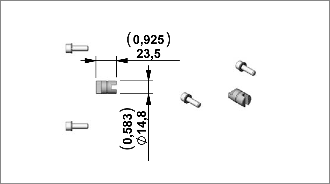
RE18306-01-30

Junction Elements for manifolds ME - MR series

Code
Type
Material Number
E67
K01X3970TR095
R932002066

D.C. Electric Motors Standard Performance

RE18306-01-31
Code
Voltage [V]
Power [W]
Duty Cycle S3% S2 min.
Thermal Switch
ULCertified
Protection index
Direction of rotation
Type
Material Number
C181
12
800
10% 2,5min
NO
YES
IP 54
<->
C1620S1081M
R930056885
C182
24
800
10% 2,5min
NO
YES
IP 54
<->
C1620S1082M
R930056886

S2 - S3 performance

Amps
S2 (min.)
S3(%) (10 min.)
50
10
25 %
100
5
10 %
150
1,5
3 %

Electric Motor C181 (12V – 800W) Diagrams

RE18306-01-32

Electric Motor C182 (24V – 800W) Diagrams

RE18306-01-33

S2 - S3 performance

Amps
S2 (min.)
S3(%) (10 min.)
25
10
25 %
50
5
10 %
75
1,5
3 %

NOTE: The values of the curves may change slightly depending on the brand / model of pump that is mounted.


Relay

RE18306-01-34

Starting Relay Standard Performance

Code
Voltage [V]
Nominal Current [A]
Short time Current [A]
Protection INDEX
ULCertified
Type
Material Number
A
Without Relay


G
12
150
350
IP66
NO
C165534000
R932000692
H
24
150
350
IP66
NO
C165535000
R932000693
L
24
150
350
IP66
YES
C165540000
R932008749

Kit Motor + Relay

RE18306-01-35
Motor + Relay
Type
Material Number
C181+relay 12V STANDARD performance
K396812181MPSF
R930061389
C182+relay 24V STANDARD performance
K396824182MPSF
R930061390
C182+relay 24V
K396824182MPSUL
R930061391

Junction Elements for D.C. Electric Motor
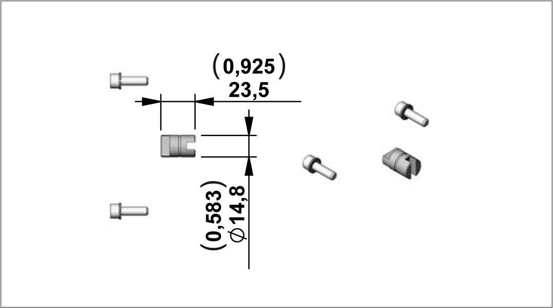
RE18306-01-36

Junction Elements for manifolds ME - MR series

Code
Type
Material Number
E67
K01X3970TR095
R932002066

D.C. Electric Motors Standard Performance

RE18306-01-37
Code
Voltage [V]
Power [W]
Duty Cycle S3% S2 min.
Thermal Switch
ULCertified
Protection index
Direction of rotation
Type
Material Number
C123
12
800
9% 4min
YES
NO
IP 54
Clockwise
C1620S1023
R932000220
C122
24
800
10% 4min
YES
NO
IP 54
Clockwise
C1620S1022
R932000219

Electric Motor C123 (12V – 800W) Diagrams

RE18306-01-38

S2 - S3 performance

Amps
S2 (min.)
S3(%) (10 min.)
50
14
35 %
100
6
12 %
150
2
3 %

Electric Motor C122 (24V – 800W) Diagrams

RE18306-01-39

S2 - S3 performance

Amps
S2 (min.)
S3(%) (10 min.)
25
16
35 %
50
7
15 %
75
2
3 %

Relay

RE18306-01-40

Starting Relay Standard Performance

Code
Voltage [V]
Nominal Current [A]
Short time Current [A]
Protection INDEX
UL Certified
Type
Material Number
A
Without Relay


G
12
150
350
IP66
NO
C165534000
R932000692
H
24
150
350
IP66
NO
C165535000
R932000693

Kit Motor + Relay

RE18306-01-41
Motor + Relay
Type
Material Number
C123+relay 12VSTANDARD performance
K396812123PSF
R930051984
C122+relay 24VSTANDARD performance
K396824122PSF
R930051967

Junction Elements for D.C. Electric Motor

RE18306-01-42

Junction Elements for manifolds ME - MR series

Code
Type
Material Number
E67
K01X3970TR095
R932002066

D.C. Electric Motors Standard Performance

RE18306-01-43
Code
Voltage (V)
Power (W)
Duty Cycle S3% S2 min.
Thermal Switch
UL Certified
Protection index
Type
Material Number
C200
24
1200
4,5% 1,2 min
no
yes
IP 54
C1620S1200
R930059616

Electric Motor C200 (24V – 1300W) Diagrams

RE18306-01-44

S2 - S3 performance

Amps
S2 (min.)
S3(%) (10 min.)
75
6
17%
100
4
11%
125
2,4
7,5%
150
1,5
5%
175
1
3,5%

NOTE: The values of the curves may change slightly depending on the brand / model of pump that is mounted.


Relay

RE18306-01-45

Starting Relay Standard Performance

Code
Voltage [V]
Nominal Current [A]
Short time Current [A]
Protection INDEX
UL Certified
Type
Material Number
A
Without Relay


H
24
150
350
IP66
NO
C165535000
R932000693
L
24
150
350
IP66
YES
C165540000
R932008749

Kit Motor + Relay

RE18306-01-46
Motor + Relay
Type
Material Number
C200+relay 24V STANDARD performance
K396824200PSF
R930071143
C200+relay 24V STANDARD performance UL certified
K396824200PSFUL
R930071144

Junction Elements for D.C. Electric Motor
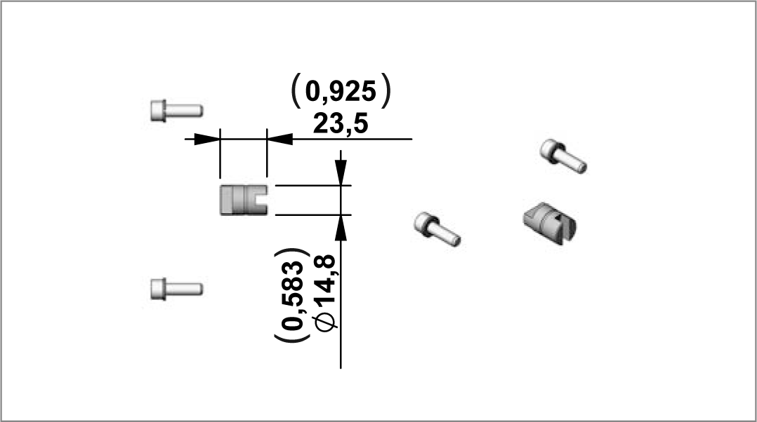
RE18306-01-47

Junction Elements for manifolds ME

Code
Type
Material Number
E71
K01X3970TR109
R932009727

NOTE: Change the standard screws supplied with the motor with the screws of the junction element E71.


D.C. Electric Motors Standard Performance

RE18306-01-48
Code
Voltage [V]
Power [W]
Duty Cycle S3% S2 min.
Thermal Switch
ULCertified
Protection index
Type
Material Number
C190
12
1600
5% 2 min
no
yes
IP 54
C1620S1090
R930056392
C191
12
1600
5% 2 min
yes
yes
IP 54
C1620S1091
R930056391
C192
24
2200
5% 2 min
no
yes
IP 54
C1620S1092
R930056390
C193
24
2200
5% 2 min
yes
yes
IP 54
C1620S1093
R930056389

Electric Motor C190-191 (12V – 1600W) Diagrams

RE18306-01-49

S2 - S3 performance

Amps
S2 (min.)
S3(%) (10 min.)
150
5,5
12%
200
3,5
8%
250
2
6%
300
1,5
4%
350
1
3%

Electric Motor C192 - C193 (24V – 2200W) Diagrams

RE18306-01-50

S2 - S3 performance

Amps
S2 (min.)
S3(%) (10 min.)
75
5
12%
100
3
7%
125
1,8
5%
150
1
4%
175
0,7
2,5%

NOTE: The values of the curves may change slightly depending on the brand / model of pump that is mounted.


Relay

RE18306-01-51

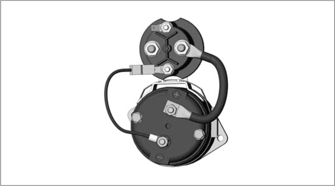
Starting Relay Standard Performance (Pict. 1)

Code
Voltage [V]
Nominal Current [A]
Short time Current [A]
Protection INDEX
UL Certified
Type
Material Number
A
Without Relay


G
12
150
350
IP66
NO
C165534000
R932000692
H
24
150
350
IP66
NO
C165535000
R932000693
L
24
150
350
IP66
YES
C165540000
R932008749

Starting Relay High Performance (silver plate contact) (Pict. 2)

Code
Voltage [V]
Nominal Current [A]
Short time Current [A]
Protection INDEX
UL Certified
Type
Material Number
A
Without Relay


C
12
150
350
IP54
NO
C165524000
R932000690
E
24
150
350
IP54
NO
C165525000
R932000691

Kit Motor + Relay

RE18306-01-52
Motor + Relay
Type
Material Number
C190+relay 12V STANDARD performance
K396812190PSCUF
R930034093
C190+relay 12V HIGH performance
K396812190C
R930034094
C191+relay 12V STANDARD performance
K396812191PSCUF
R930034095
C191+relay 12V HIGH performance
K396812191C
R930034097
C192+relay 24V STANDARD performance
K396824192PSCUF
R930035261
C192+relay 24V STANDARD performance UL certified
K396824192PSUL
R930034098
C192+relay 24V HIGH performance
K396824192E
R930034101
C193+relay 24V STANDARD performance
K396824193PSCUF
R930034102
C193+relay 24V STANDARD performance UL certified
K396824193PSUL
R930035112
C193+relay 24V HIGH performance
K396824193E
R930035252

Plastic Protection

RE18306-01-53
Code
 
Type
Material Number
0
Without Protection
-
-
1
With Protection
K229701000
R932002246

Kit for assembly plastic protection

Type
Material Number
K01K211565000
R930059147

Junction Elements for D.C. Electric Motor
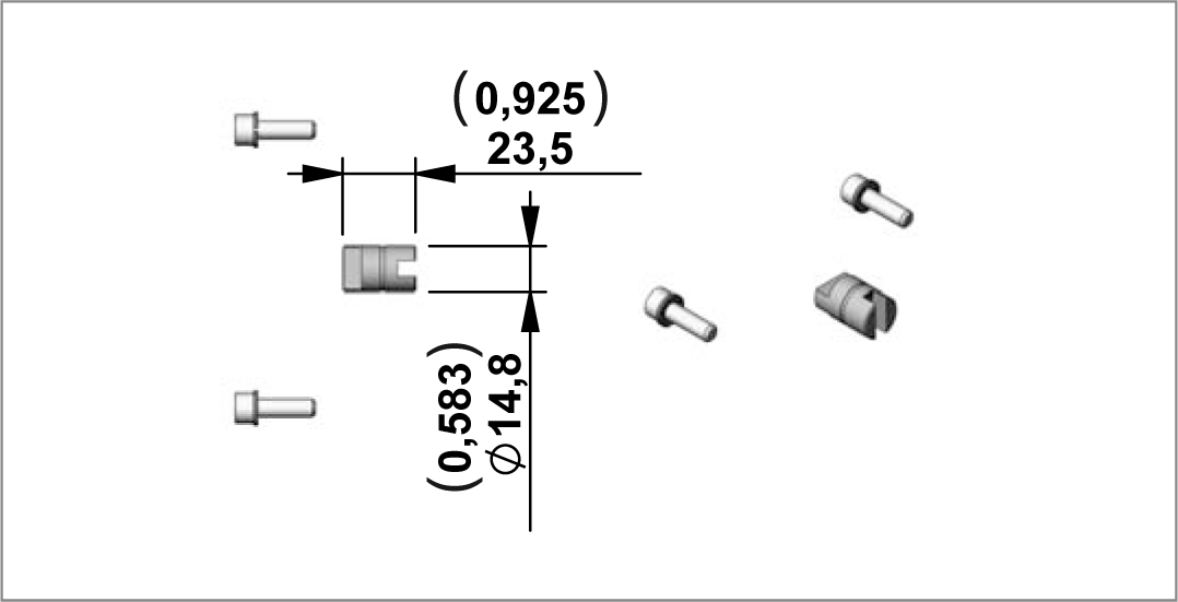
RE18306-01-54

Junction Elements for manifolds ME series

Code
Type
Material Number
E31
K01K3970TR008
R932001907
RE18306-01-55
Code
Voltage [V]
Power [W]
Duty Cycle S3% S2 min.
Thermal Switch
ULCertified
Protection index
Type
Material Number
C91
12
1600
7,5% 3 min
NO
NO
IP 54
C162090000
R932000272
C102
12
1600
7,5% 3 min
YES
NO
IP 54
C1620S1002
R932000201
C92
24
2200
4,5% 1,2 min
NO
NO
IP 54
C162091000
R932000273
C103
24
2200
4,5% 1,2 min
YES
NO
IP 54
C1620S1003
R932000202

Electric Motor C91-C102 (12V – 1600W) Diagrams

RE18306-01-56

S2 - S3 performance

Amps
S2 (min.)
S3(%) (10 min.)
150
5,5
12%
200
3,5
8%
250
2
6%
300
1,5
4%
350
1
3%

Electric Motor C92-C103 (24V – 2200W) Diagrams

RE18306-01-57

S2 - S3 performance

Amps
S2 (min.)
S3(%) (10 min.)
75
5
12%
100
3
7%
125
1,8
5%
150
1
4%
175
0,7
2,5%

NOTE: The values of the curves may change slightly depending on the brand / model of pump that is mounted.


Relay

RE18306-01-58

Starting Relay Standard Performance (Pict. 1)

Code
Voltage [V]
Nominal Current [A]
Short time Current [A]
Protection INDEX
UL Certified
Type
Material Number
A
Without Relay


G
12
150
350
IP66
NO
C165534000
R932000692
H
24
150
350
IP66
NO
C165535000
R932000693

Starting Relay High Performance (silver plate contact) (Pict. 2)

Code
Voltage [V]
Nominal Current [A]
Short time Current [A]
Protection INDEX
UL Certified
Type
Material Number
A
Without Relay


C
12
150
350
IP54
NO
C165524000
R932000690
E
24
150
350
IP54
NO
C165525000
R932000691

Kit Motor + Relay

RE18306-01-59
Motor + Relay
Type
MaterialNumber
C91+relay 12V STANDARD performance
K39681291PSCUF
R932007960
C91+relay 12V HIGH performance
K39681291CF
R932002749
C102+relay 12V STANDARD performance
K396812102PSCUF
R932007969
C102+relay 12V HIGH performance
K396812102CF
R932002715
C92+relay 24V STANDARD performance
K39682492PSCUF
R932007961
C92+relay 24V HIGH performance
K39682492EF
R932002818
C103+relay 24V STANDARD performance
K396824103PSCUF
R932007968
C103+relay 24V HIGH performance
K396824103EF
R932002771

Plastic Protection

RE18306-01-60
Code
 
Type
Material Number
0
Without Protection
-
-
1
With Protection
K229701000
R932002246

Kit for assembly plastic protection

Type
Material Number
K01K211518000
R932009439

Junction Elements for D.C. Electric Motor
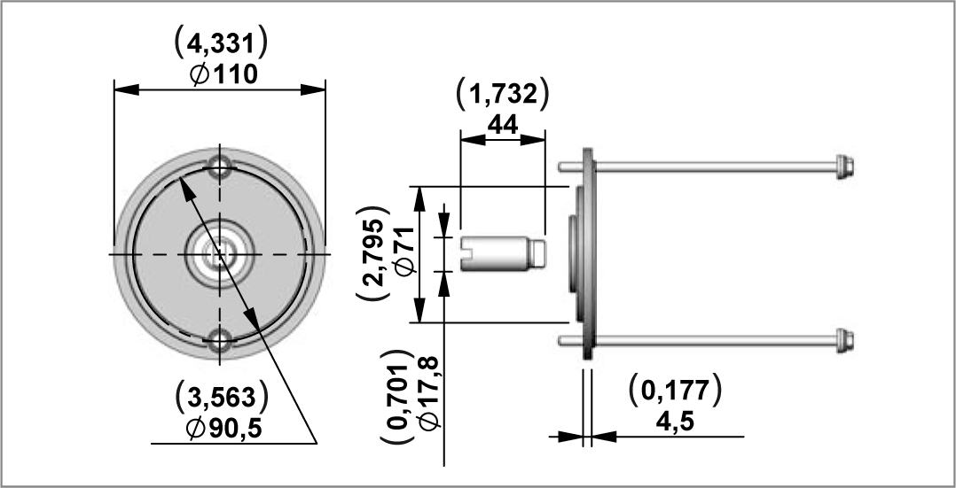
RE18306-01-61

Junction Elements for manifolds ME series

Code
Type
Material Number
E31
K01K3970TR008
R932001907

M52 - M55

RE18306-01-62

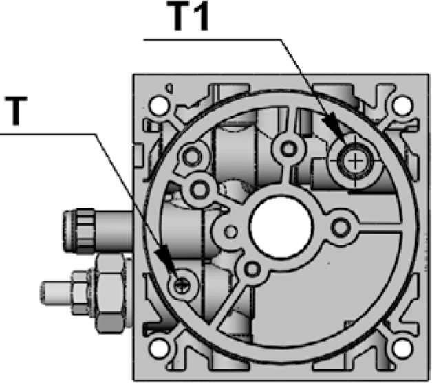
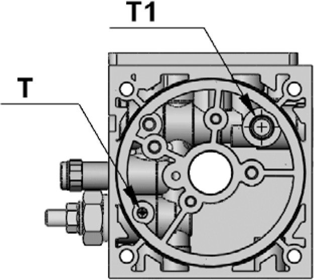
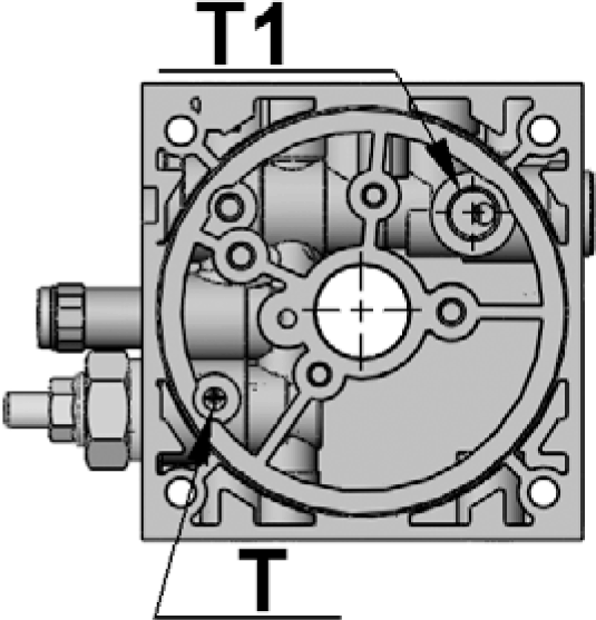
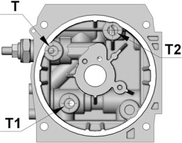
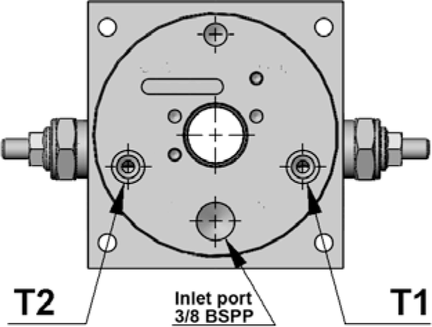
View Manifold Tank side

RE18306-01-63

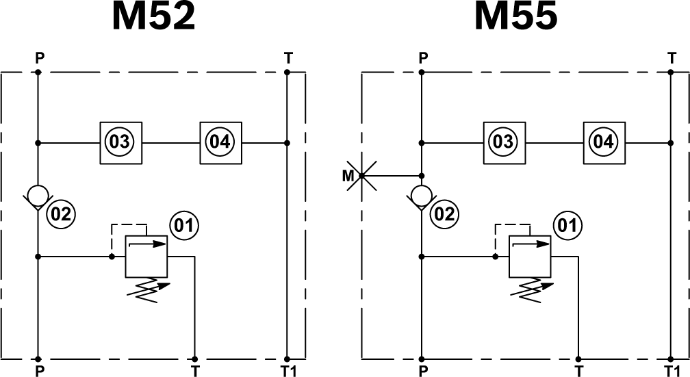
M52

Manifold Code with Relief Valve Pressure Range
Presure Range bar (psi)
Type
Material Number
M52/05
10-70 (145-1015)
452A000
R932008635
M52/10
35-140 (508-2030)
452B000
R932008636
M52/20
105-210 (1523-3046)
452C000
R932008637
M52/35
175-350 (2538-5076)
452D000
R932008638

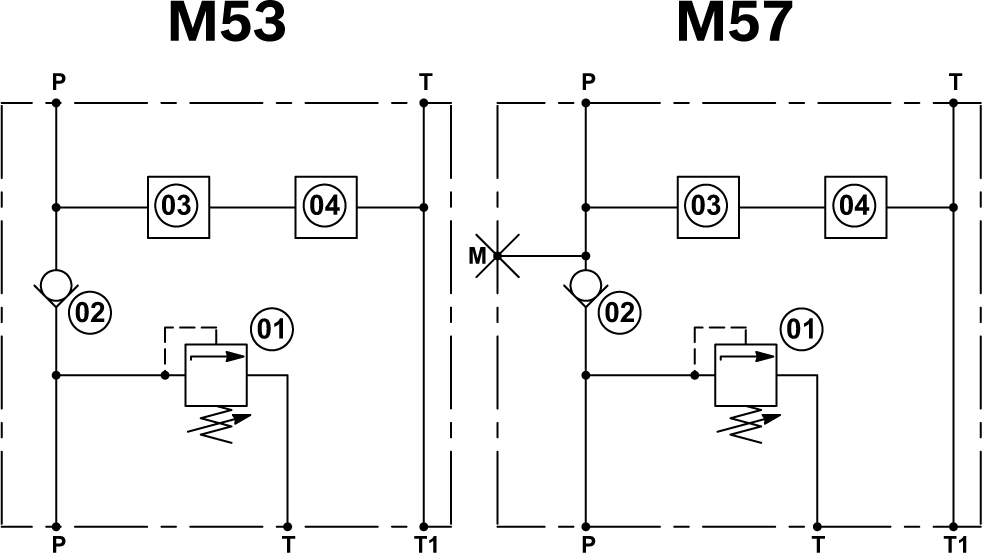
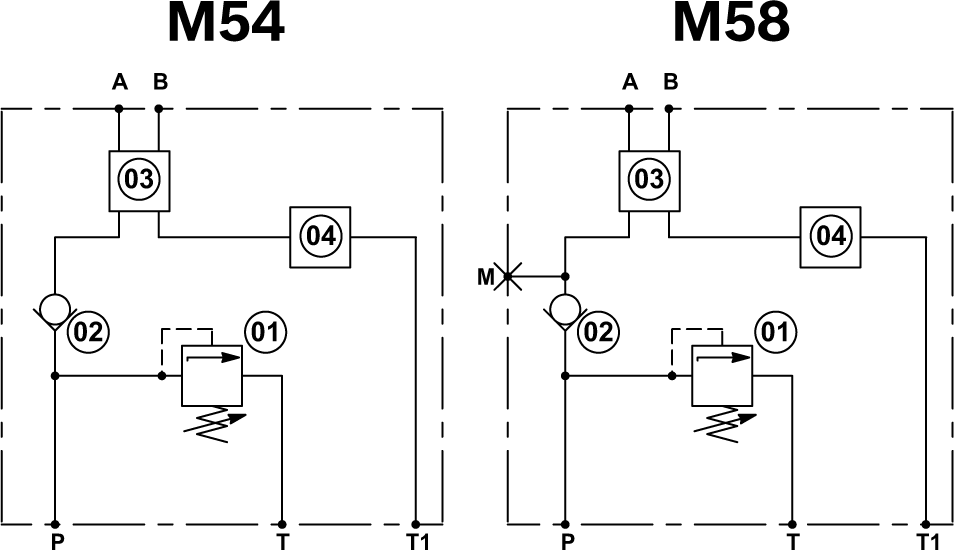
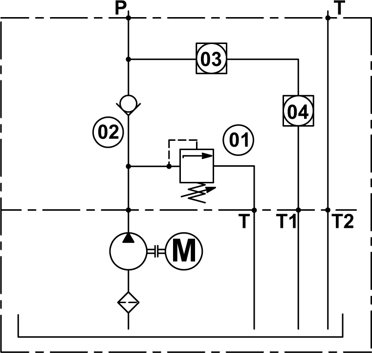
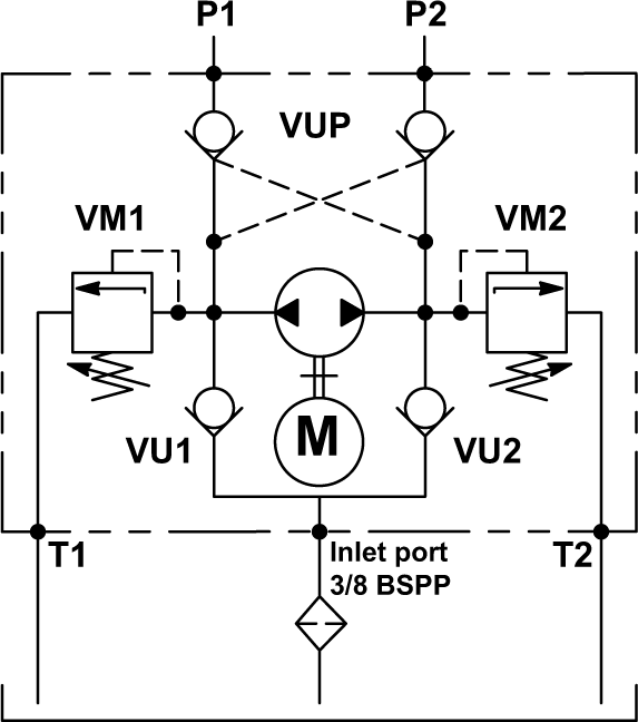
Manifold Hydraulic Diagram

RE18306-01-64

M55

Manifold Code with Relief Valve Pressure Range
Presure Range bar (psi)
Type
Material Number
M55/05
10-70 (145-1015)
455A000
R932008639
M55/10
35-140 (508-2030)
455B000
R932008640
M55/20
105-210 (1523-3046)
455C000
R932008641
M55/35
175-350 (2538-5076)
455D000
R932008642

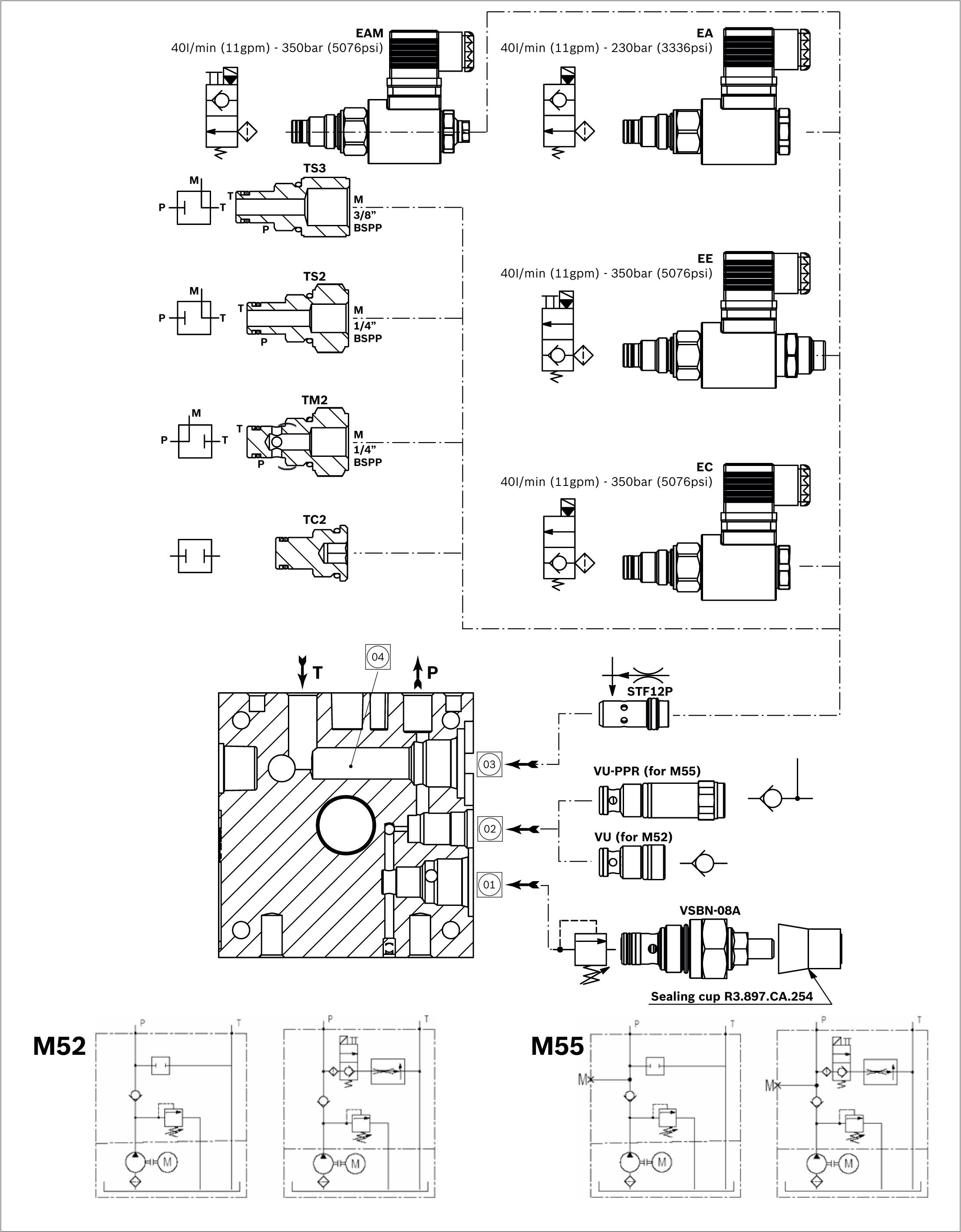
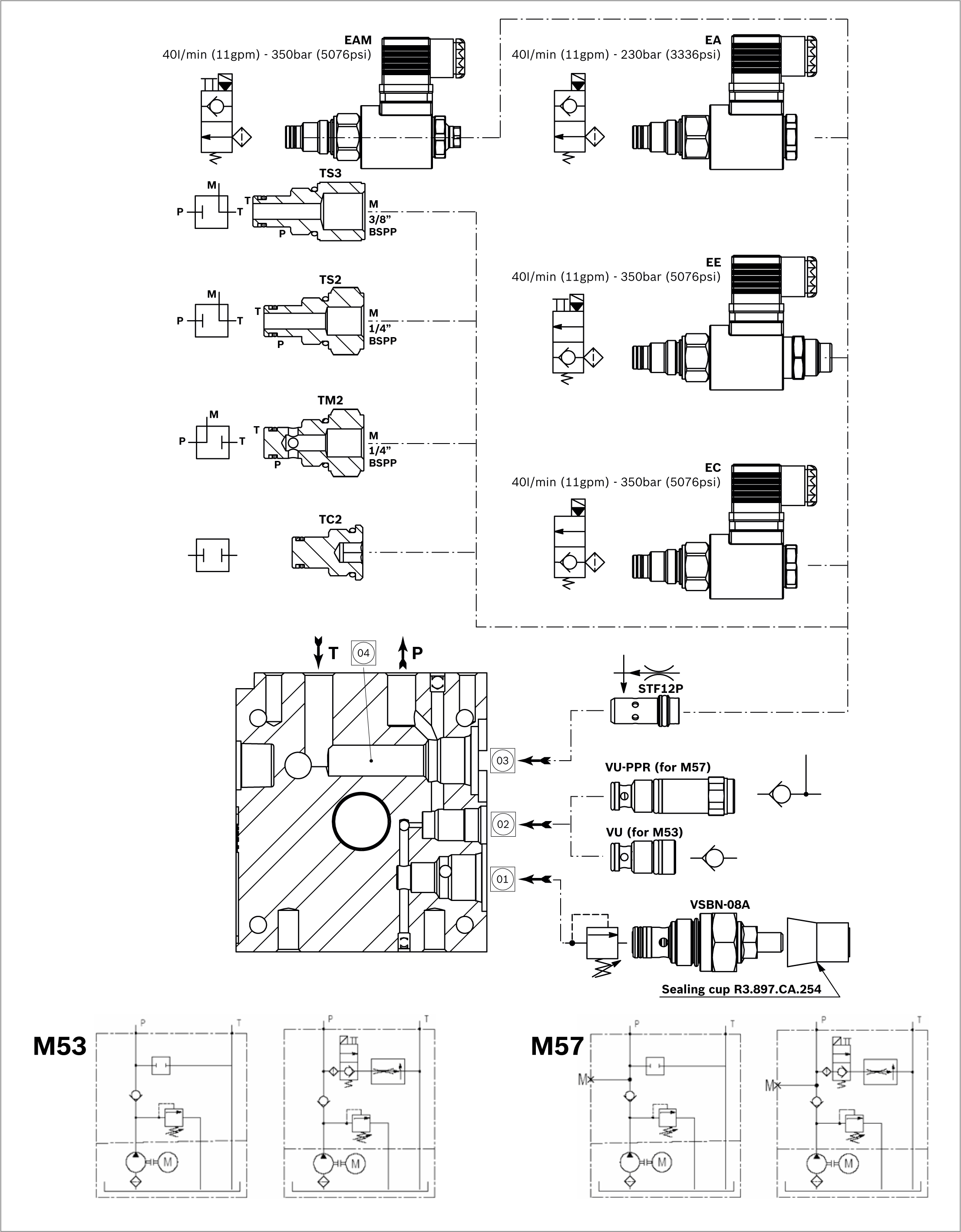
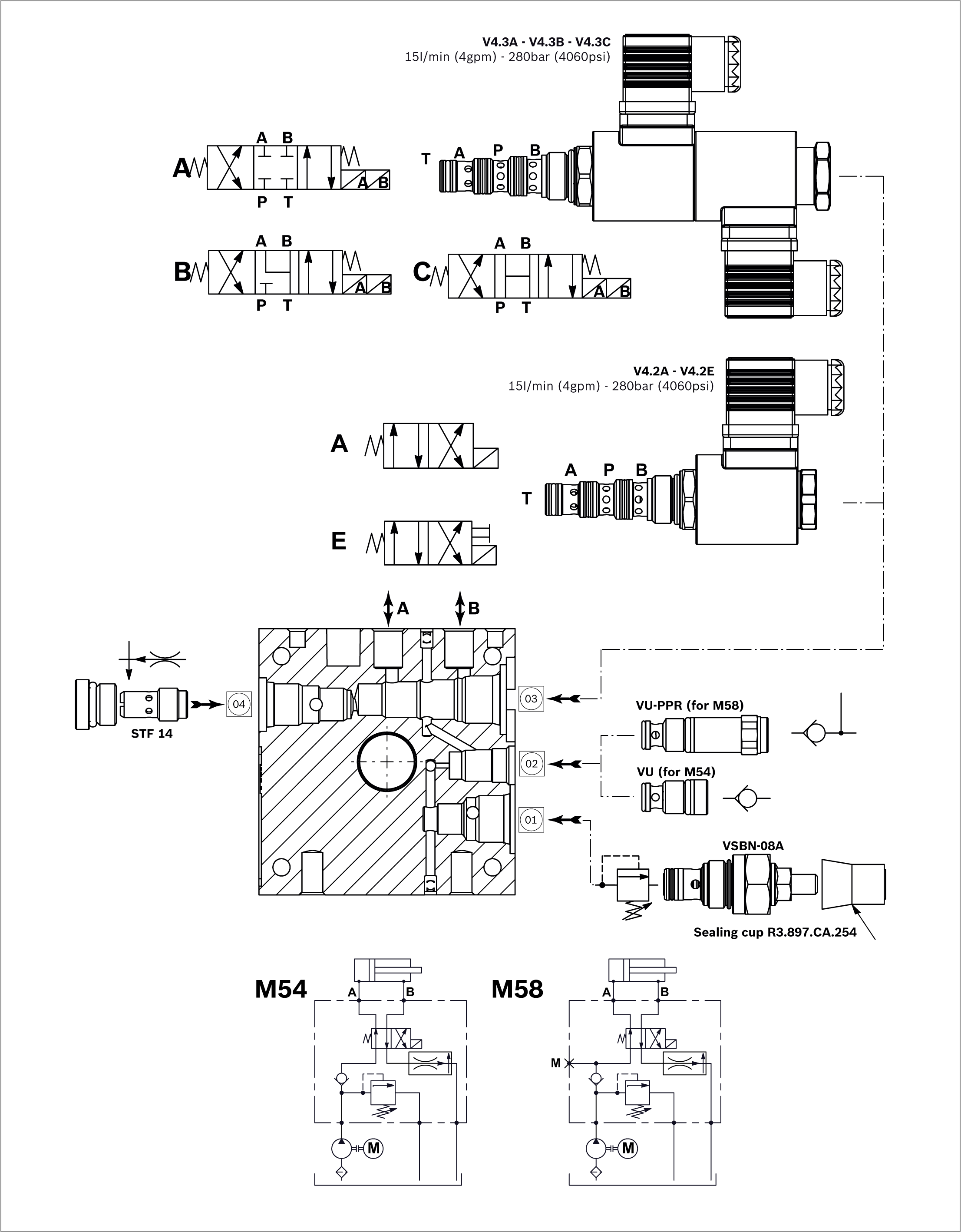
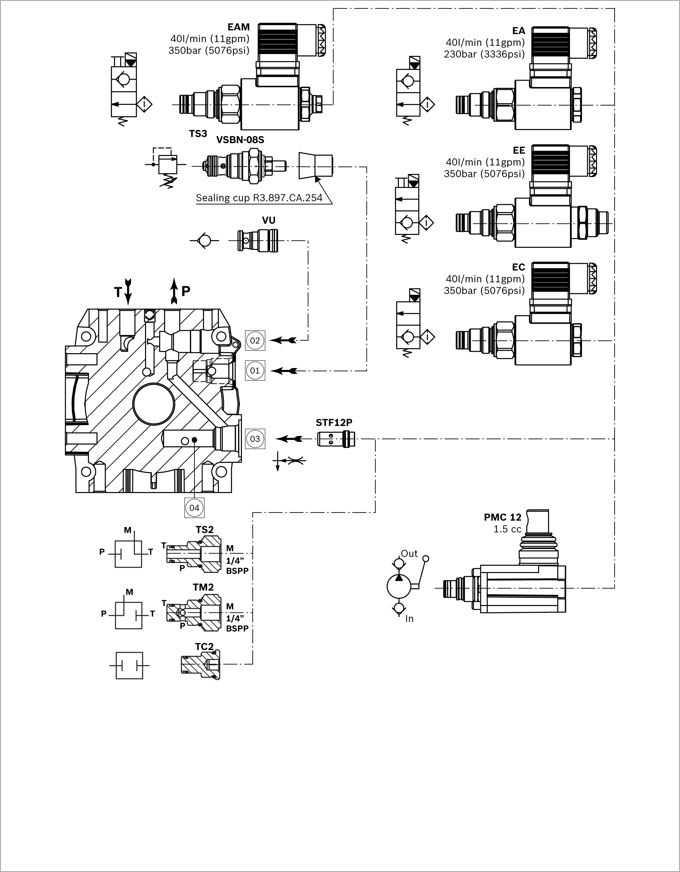
Assembly Diagram

RE18306-01-65

M53 - M57

RE18306-01-66

View Manifold Tank side

RE18306-01-67

M53

Manifold Code with Relief Valve Pressure Range
Presure Range bar (psi)
Type
Material Number
M53/05
10-70 (145-1015)
453A000
R932008627
M53/10
35-140 (508-2030)
453B000
R932008628
M53/20
105-210 (1523-3046)
453C000
R932008629
M53/35
175-350 (2538-5076)
453D000
R932008630

Manifold Hydraulic Diagram

RE18306-01-68

M57

Manifold Code with Relief Valve Pressure Range
Presure Range bar (psi)
Type
Material Number
M57/05
10-70 (145-1015)
457A000
R932008631
M57/10
35-140 (508-2030)
457B000
R932008632
M57/20
105-210 (1523-3046)
457C000
R932008633
M57/35
175-350 (2538-5076)
457D000
R932008634

Assembly Diagram

RE18306-01-69

M54 - M58

RE18306-01-70

View Manifold Tank side

RE18306-01-71

M54

Manifold Code with Relief Valve Pressure Range
Presure Range bar (psi)
Type
Material Number
M54/05
10-70 (145-1015)
454A000
R932008619
M54/10
35-140 (508-2030)
454B000
R932008620
M54/20
105-210 (1523-3046)
454C000
R932008621
M54/35
175-350 (2538-5076)
454D000
R932008622

Manifold Hydraulic Diagram

RE18306-01-72

M58

Manifold Code with Relief Valve Pressure Range
Presure Range bar (psi)
Type
Material Number
M58/05
10-70 (145-1015)
458A000
R932008623
M58/10
35-140 (508-2030)
458B000
R932008624
M58/20
105-210 (1523-3046)
458C000
R932008625
M58/35
175-350 (2538-5076)
458D000
R932008626

Assembly Diagram

RE18306-01-73

A16

RE18306-01-74

View Manifold Tank side

RE18306-01-75

A16

Manifold Code with Relief Valve Pressure Range
Presure Range bar (psi)
Type
Material Number
A16/05
10-55 (145-798)
116A000A
R930052174
A16/10
35-100 (508-1450)
116B000A
R930052184
A16/20
90-250 (1305-3626)
116C000
R932008693

Manifold Hydraulic Diagram

RE18306-01-76

Assembly Diagram

RE18306-01-77

10

RE18306-01-78

View Manifold Tank side

RE18306-01-79

10

Manifold Code with Relief Valve Pressure Range
Presure Range bar (psi)
Type
Material Number
A10/05
10-55 (145-798)
810A000A
R930053852
A10/10
35-100 (508-1450)
810B000A
R930053853
A10/20
90-250 (1305-3626)
810C000
R932009780

Manifold Hydraulic Diagram

RE18306-01-80

NOTE: In this central manifold use only reversible pump “R” series.

NOTE: In the central manifold MR series is possible connect only the following motors: DC motor code: C177 - C178 - C179 - C180 - C181 - C182 AC motor from size IEC56 to size IEC71.


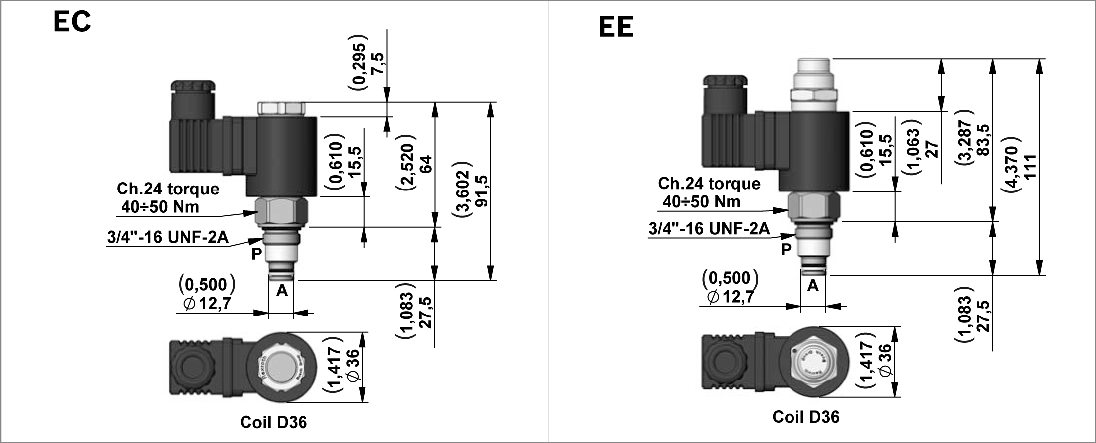
EC-EE Series

RE18306-01-81

2 Way Pilot Operated Solenoid Valves, Normally Closed for D.C. current

Code
Type
Material Number
EC
OD150718A000000
R930058338
EE
OD150718DP00000
R930058529

Technical Data

General
Operating time
ms
Opening 50, Closing 100
Max. working pressure
bar (psi)
350 (5076)
Max. flow
l/min (gpm)
40 (11)

Description

Description

This is a standard 2 way pilot operated valves poppet style.

  • Only for D.C. current.
  • Internal leakage: see technical data.
  • Minimum operating voltage: 90% of nominal.
  • Screen on P 300 Micron.
  • Screw Type Emergency on EE.

Valve symbol
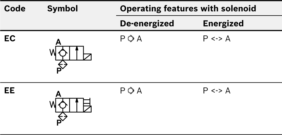
RE18306-01-82

D36 Coil Voltage Available

Voltage
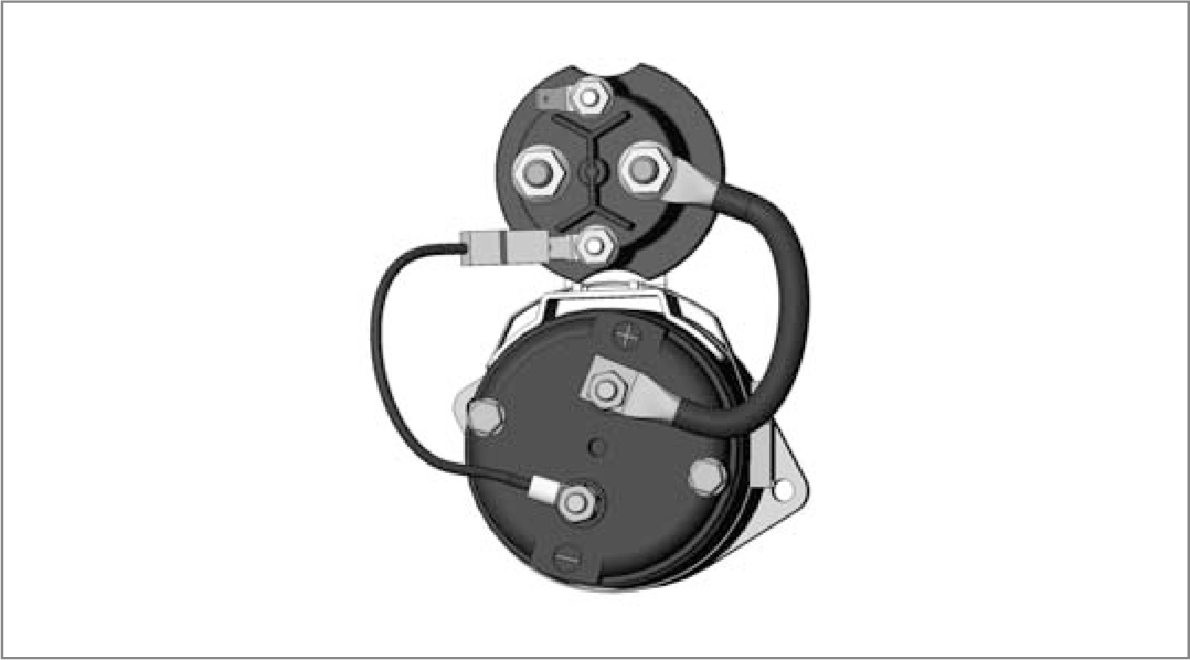
12 Volts D.C.
24 Volts D.C.
48 Volts D.C.
96 Volts D.C.
205 Volts D.C.

NOTE: For more info see Data Sheet RE18323-25


EA-EAM Series
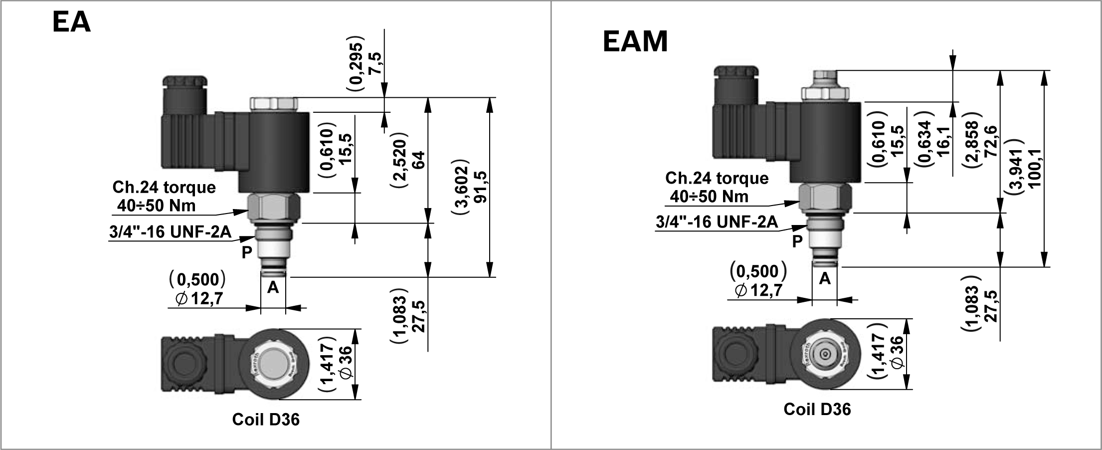
RE18306-01-83

2 Way Pilot Operated Solenoid Valves, Normally Open

Code
Type
Material Number
EA
OD150818A000000
R930058337
EAM
OD150818B000000
R930058340

Technical Data

General
Max. working pressure
bar (psi)
350(5000)
Max. flow
l/min (gpm)
40 (11)

Description

Description

This is a standard 2 way pilot operated valves poppet style.

  • Only for D.C. current.
  • Internal leakage: see technical data.
  • Minimum operating voltage: 90% of nominal.
  • Screen on P 300 Micron.
  • Push Type Emergency on EAM.

Valve symbol
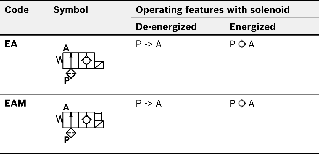
RE18306-01-84

D36 Coil Voltage Available

Voltage
12 Volts D.C.
24 Volts D.C.
48 Volts D.C.
96 Volts D.C.
205 Volts D.C.

NOTE: For more info see Data Sheet RE18323-26


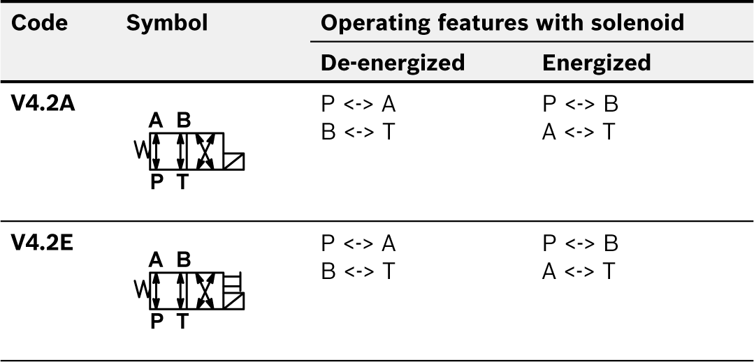
V4.2 Series
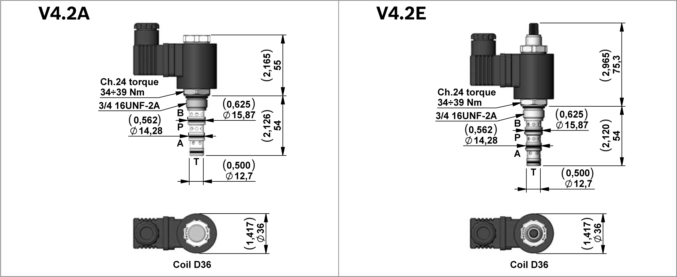
RE18306-01-85

4 Way 2 Position Solenoid Valves Spool Type

Code
Type
Material Number
V4.2A
OD144058A000000
R930058339
V4.2E
OD144058D000000
R930058713

Technical Data

General
Max. workingpressure
bar (psi)
280 (4060)
Max. flow
l/min (gpm)
20 (5)

Description

Description

4 Way 2 Position Solenoid Valves Spool Type

  • Only for D.C. current.
  • Minimum operating voltage: 90% of nominal.
  • Screw Type Emergency on V4.2E.

Valve symbol
RE18306-01-86

D36 Coil Voltage Available

Voltage
12 Volts D.C.
24 Volts D.C.
48 Volts D.C.
96 Volts DC
205 Volts DC

NOTE: For more info see Data Sheet RE18324-09


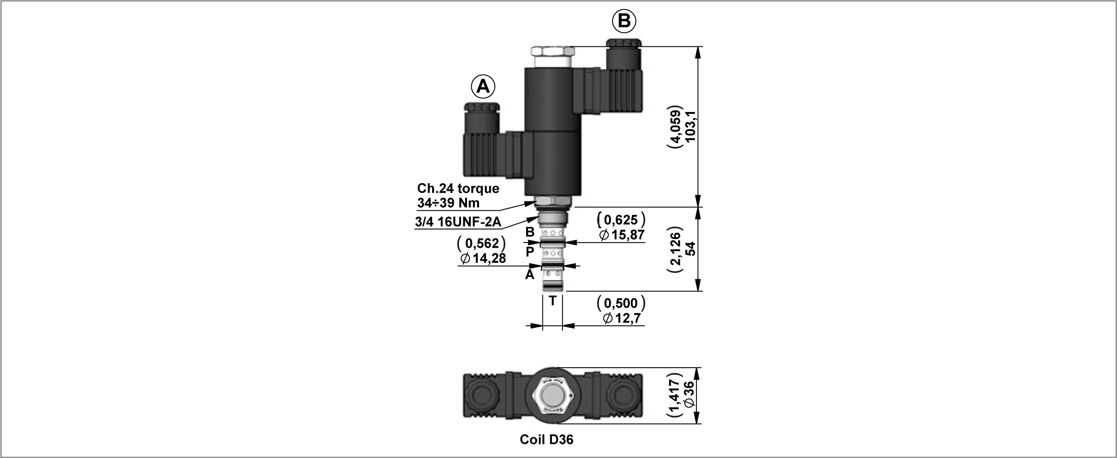
V4.3 Series
RE18306-01-87

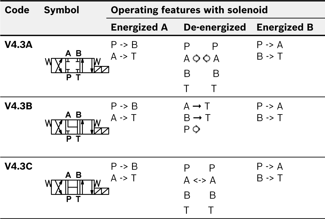
4 Way 3 Position Solenoid Valves Spool Type

Code
Type
Material Number
V4.3A
OD143158A000000
R930063202
V4.3B
OD143258A000000
R930063203
V4.3C
OD143458A000000
R930063205

Technical Data

General
Max. workingpressure
bar (psi)
280 (4060)
Max. flow
l/min (gpm)
15 (4)

Description

4 Way 3 Position Solenoid Valves Spool Type

Only for D.C. current.

Minimum operating voltage: 90% of nominal.


Valve symbol
RE18306-01-88

D36 Coil Voltage Available

Voltage
12 Volts D.C.
24 Volts D.C.
48 Volts D.C.
96 Volts DC
205 Volts DC

NOTE: For more info see Data Sheet RE18324-10


Technical Data

RE18306-01-89

Weight: 0.18 kg (0.40 lbs)

Power: 20 W

Heat insulation Class H: 180°C (356°F)

Ambient temperature range: -30/+90°C (-22/+194°F)

Further performance limits in terms of temperature and voltage fluctuations: please refer to data sheet of the solenoid valve where D36 coil is mounted.


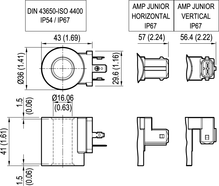
Coils D36 DIN 43650

CODE
VOLTAGE
HEAT INSULATION CLASS
TYPE
MATERIAL NUMBER
OB
12 Volts D.C.
H (180 °C) (356 °F)
OD02360130OB00
R901393412
OC
24 Volts D.C.
H (180 °C) (356 °F)
OD02360130OC00
R901393577
OD
48 Volts D.C.
H (180 °C) (356 °F)
OD02360130OD00
R901394117
OU*
96 Volts D.C.
H (180 °C) (356 °F)
OD02360130OU00
R901394229
AH*
205 Volts D.C.
H (180 °C) (356 °F)
OD02360130AH00
R901394231

NOTE: * OU and AH versions especially designed in cases of AC supply voltage (respectively for 110AC and 220 AC) to be used in conjunction with connector with circuit including wave rectifier. Ambient temperature range for OU and AH versions: -30°C / + 75°C


Coils D36 AMP H

CODE
VOLTAGE
HEAT INSULATION CLASS
TYPE
MATERIAL NUMBER
OBA
12 Volts D.C.
H (180 °C) (356 °F)
OD02360730OB00
R901435508
OCA
24 Volts D.C.
H (180 °C) (356 °F)
OD02360730OC00
R901435506

Coils D36 AMP V

CODE
VOLTAGE
HEAT INSULATION CLASS
TYPE
MATERIAL NUMBER
OBAV
12 Volts D.C.
H (180 °C) (356 °F)
OD0236073POB00
R901394950
OCAV
24 Volts D.C.
H (180 °C) (356 °F)
OD0236073POC00
R901394955

RE18306-01-90

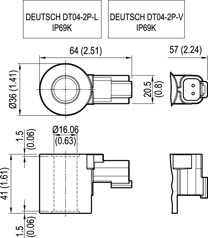
Coils D36 Deutsch L

CODE
VOLTAGE
HEAT INSULATION CLASS
TYPE
MATERIAL NUMBER
OBDL
12 Volts D.C.
H (180 °C) (356 °F)
OD02362030OB00
R901435524
OCDL
24 Volts D.C.
H (180 °C) (356 °F)
OD02362030OC00
R901435526

Coils D36 Deutsch V

CODE
VOLTAGE
HEAT INSULATION CLASS
TYPE
MATERIAL NUMBER
OBD
12 Volts D.C.
H (180 °C) (356 °F)
OD0236203POB00
R901394391
OCD
24 Volts D.C.
H (180 °C) (356 °F)
OD0236203POC00
R901394393

RE18306-01-91

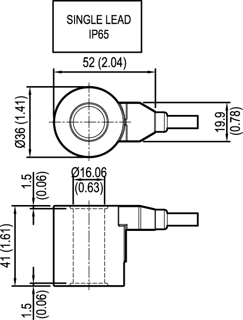
Coils D36 Single Lead

CODE
VOLTAGE
HEAT INSULATION CLASS
TYPE
MATERIAL NUMBER
OBL
12 Volts D.C.
H (180 °C) (356 °F)
OD02360G03OB00
R901435529
OCL
24 Volts D.C.
H (180 °C) (356 °F)
OD02360G03OC00
R901435533

NOTE: For more info see Data Sheet RE18325-90


CONNECTOR IP67 - EN175000 (DIN 4350-A) / ISO 4400

RE18306-01-92
Ambient temperature - Standard
°C (°F)
- 20 to + 60 (-4 to +140°F)
Type of protection according to DIN 40050
IP67 with cable socket mounted and locked
Operating voltage
V
Choose the proper ordering code according to the circuit
Maximum operating current
Standard
A
16
 
With rectifier
A
1
Number of pins
2 + PE
Clamping range for cables having an outer diameter of
mm (inch)
5, up to 10 (0,2 up to 0,4)
Cable entry
Pg9 / Pg11 (unified)
Maximum cable cross-section
mm2 (inch2)
1.5 (0,002)

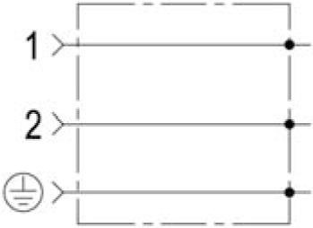
Standard Circuit

RE18306-01-93
Code
Colour
Cable entry
Type
Material Number
WC
Without Connector
CS
black
Pg9 / Pg11
OD016901000000
R934004344
 
grey
Pg9 / Pg11
OD016901000003
R934004346

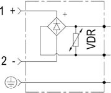
Circuit with VDR + Wave Rectifier

RE18306-01-94
Code
Voltage V
Diode Capacity Imax
Colour
Cable entry
Type
Material Number
 
AC
DC


CR
230
1A
black
Pg9 / Pg11
OD01690201OZ00
R934004353

NOTE: Diode with capacity max 1 Amp.


PMC12 Order Code for Lever (only for manifold code A16)

RE18306-01-95
Type
Material Number
K250113000
R932002448

Technical Data

General
Max. workingpressure
bar (psi)
300 (4500)
Displacement
cm³
1.5

Hand pump (1.5cc)

Code
Diagram
Type with lever
Material Number with lever
PMC12
K01V388540LV190
R932009298

Plug for Cavity

RE18306-01-97

1/4” Auxiliary Return Port

RE18306-01-98

3/8” Auxiliary Return Port

RE18306-01-99

1/4” Auxiliary Pressure Port

RE18306-01-100

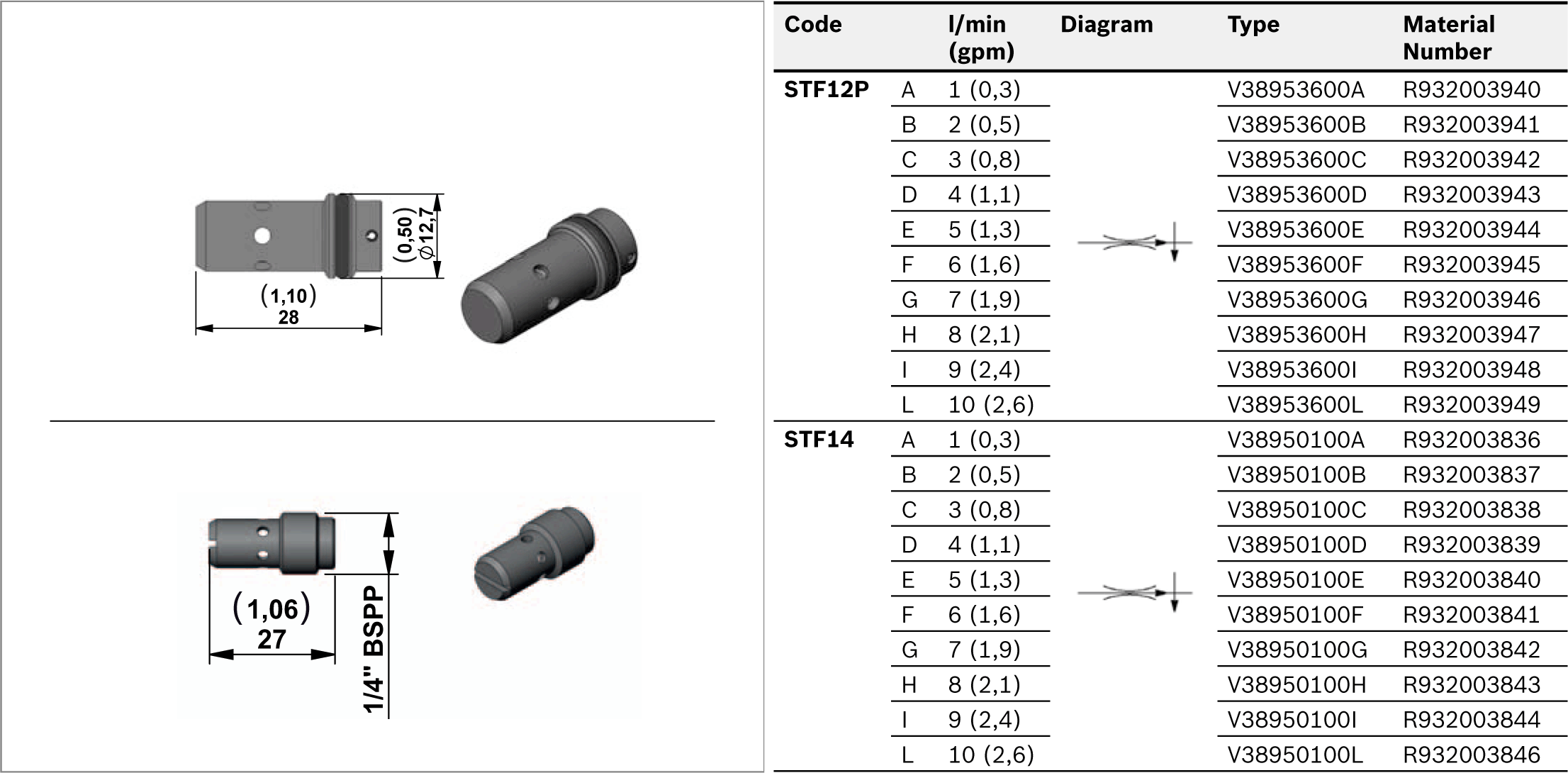
Flow Control Valves Pressure Compensated
RE18306-01-101

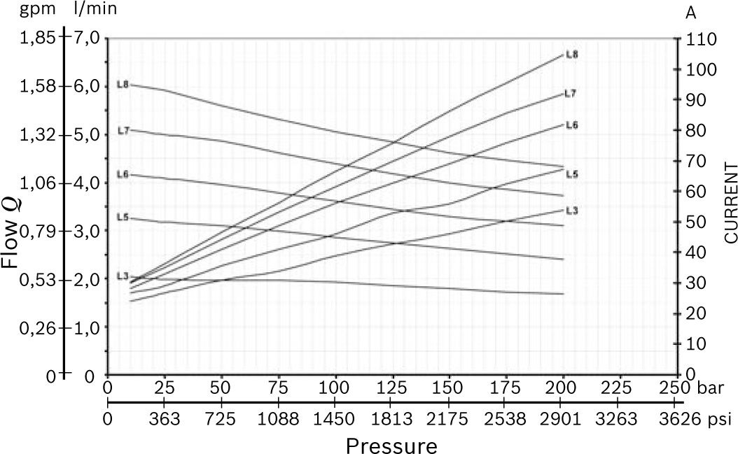
Gear Pumps Group 0.5 for ME

RE18306-01-102
Code
Displacement cc/rev
Flow at 1500 rpm l/min (gpm)
P2 bar (psi)
P3 bar (psi)
Type
Material Number
L1
0,18
0,27 (0,07)
190 (2756)
230(3336)
K01CV641L1000
R932007490
L2
0,25
0,37 (0,10)
190 (2756)
230(3336)
K01CV641L200C
R932007491
L3
0,50
0,75 (0,20)
190 (2756)
230(3336)
K01CV641L300C
R932007492
L5
0,75
1,12 (0,30)
190 (2756)
230(3336)
K01CV641L500C
R932007494
L6
1,00
1,50 (0,40)
190 (2756)
230(3336)
K01CV641L600C
R932007495
L7
1,25
1,87 (0,50)
190 (2756)
230(3336)
K01CV641L700C
R932007496
L8
1,50
2,25 (0,60)
190 (2756)
230(3336)
K01CV641L800C
R932007497

Reversible Gear Pumps Group 0.5 for MR

RE18306-01-103
Code
Displacement cc/rev
Flow at 1500 rpm l/min (gpm)
P2 bar (psi)
P3 bar (psi)
Type
Material Number
R1
0,24
0,36 (0,09)
170 (2465)
190 (2756)
C1641R100M
R932000678
R2
0,48
0,72 (0,19)
170 (2465)
190 (2756)
C1641R200M
R932000681
R3
0,61
0,92 (0,24)
170 (2465)
190 (2756)
C1641R300M
R932000682
R4
0,84
1,26 (0,33)
170 (2465)
190 (2756)
C1641R400M
R932000683
R5
0,97
1,50 (0,40)
170 (2465)
190 (2756)
C1641R500M
R932000684
R6
1,22
1,83 (0,48)
170 (2465)
190 (2756)
C1641R6000
R932008245
R7
1,50
2,25 (0,59)
170 (2465)
190 (2756)
C1641R700M
R932000685

NOTE: All pumps have anti-clockwise rotation.


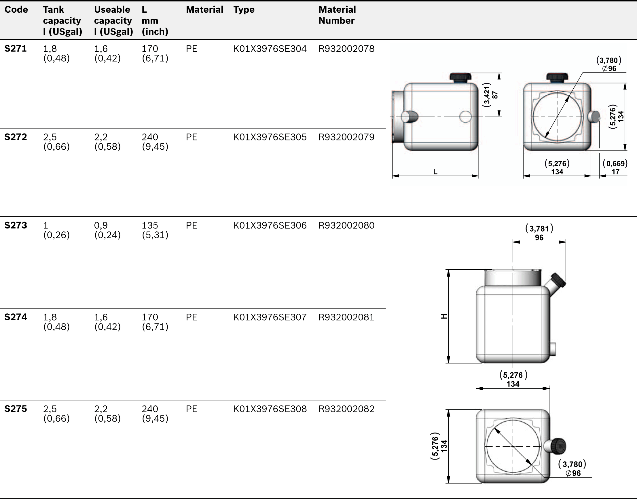
Technical Data for Plastic Tanks

RE18306-01-104
Temperature range
°C (°F)
-15....+70 (5….158)
Materials
PE=Polyethylene - PP=Polypropilene
Seal
For all the plastic Tanks use O-ring 4350 (Ø88,5x3,53)Code: 110201875000000Material-Number: R932000191

Plastic Tanks

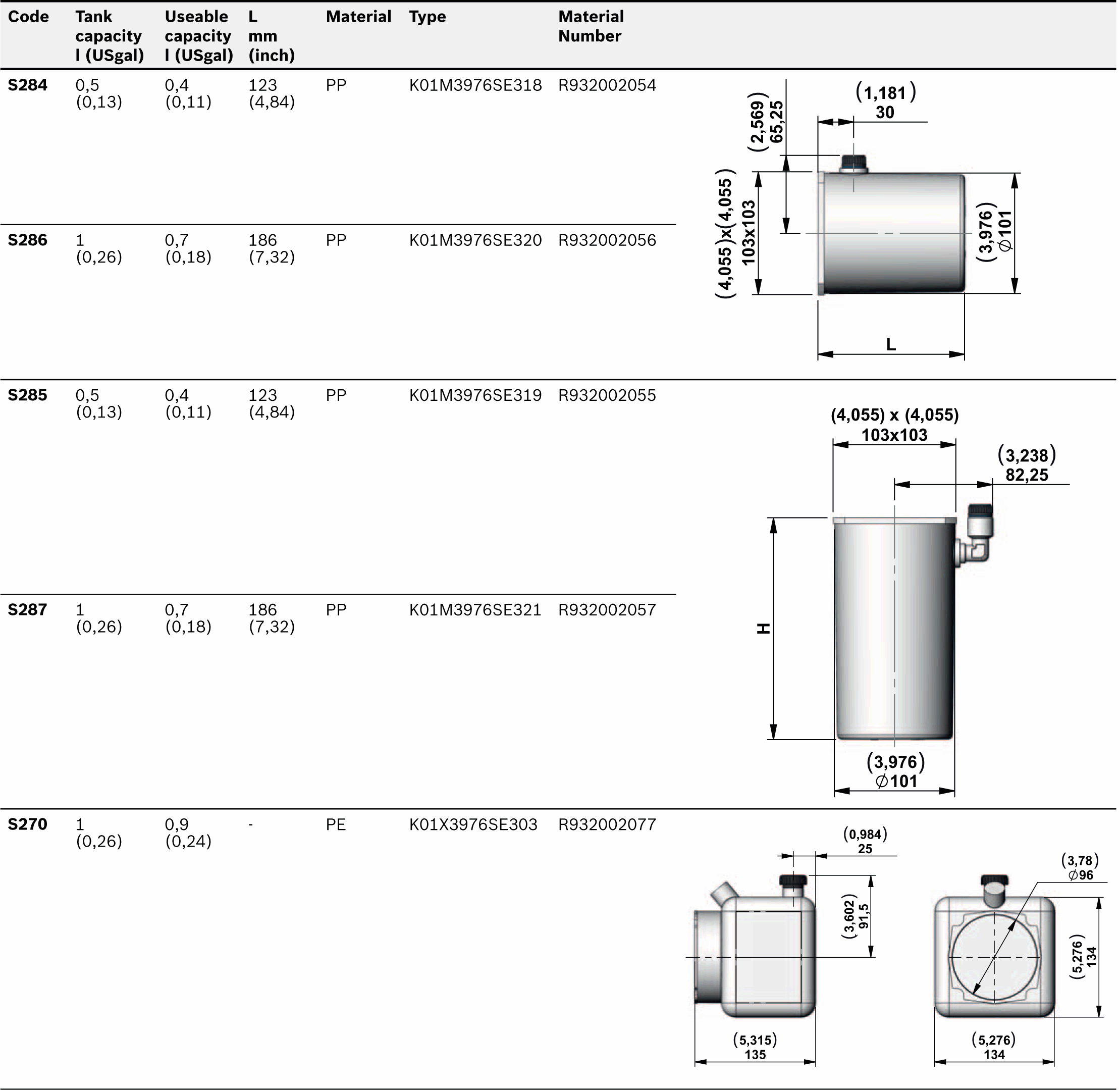
RE18306-01-105

Assembly Kit for Plastic Tank - ME

RE18306-01-106
Code
Type
Material Number
S270 - S271 - S272 - S273 - S274 - S275
K2501VT005
R932002435
S284 - S285 - S286 - S287
K2501VT009
R932002438

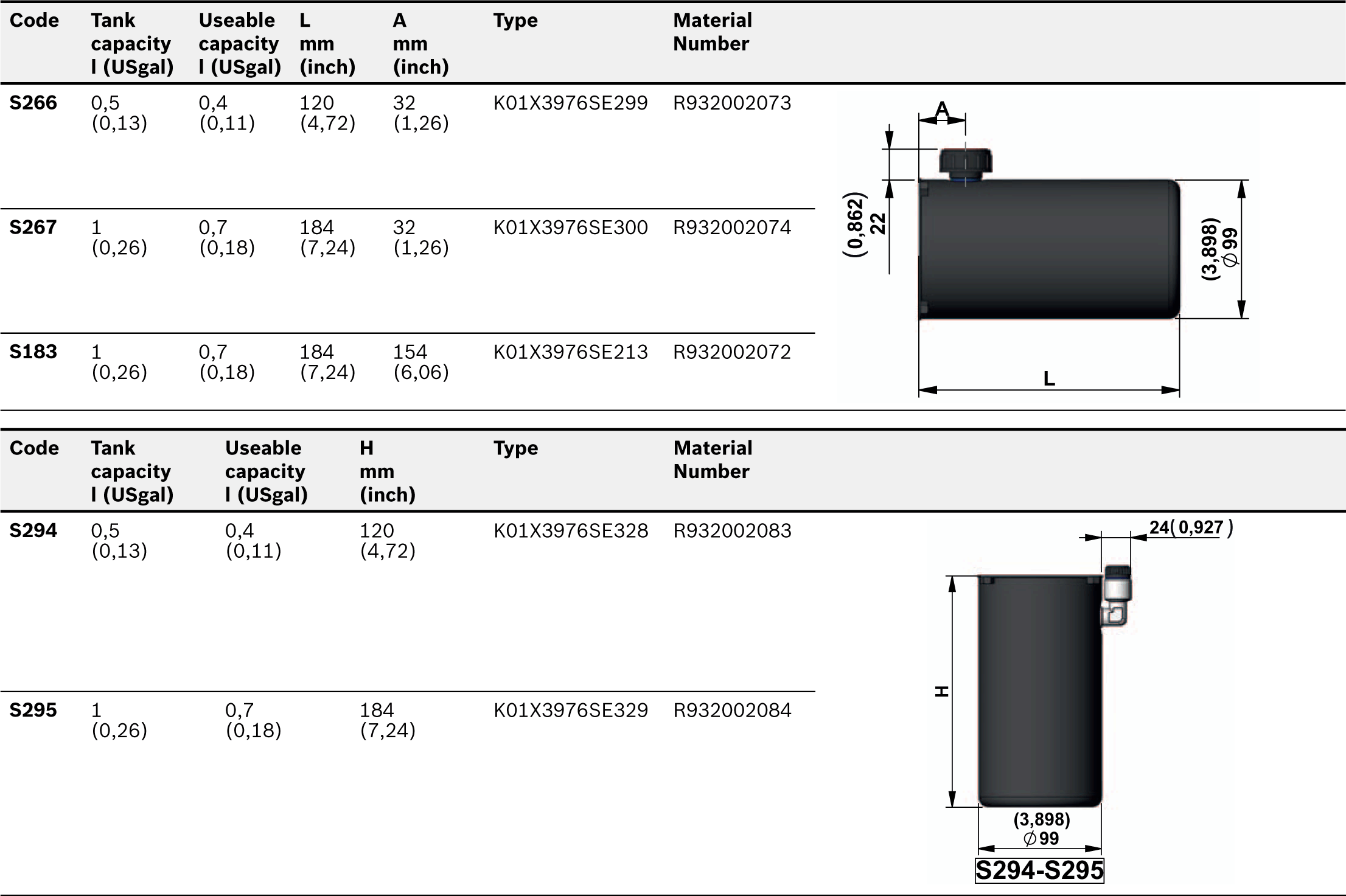
Technical Data for Steel Tanks

Temperature range
°C (°F)
-15....+80 (5….176)
Materials
Steel
Colors
Black paint finish
Seal
For all the steel tanks with Ø99 is necessary to use O-Ring 4350 (Ø88,5x3,53) on the central manifold.Code:110201875000000 - Material-Number:R932000191.If is necessary to use a tank designed for KE-K (Ø123mm) must use the O-ring 4350 on the manifold and add the flange S81.

Collar for Tanks

RE18306-01-107

Steel Tanks

RE18306-01-108

Steel Tanks

RE18306-01-109

Steel Tanks

RE18306-01-110

Steel Tanks

RE18306-01-111

Steel Tanks

RE18306-01-112

NOTE: In order to avoid to support the weight of motor by the collar of the tank when the tanks with fi xing brakets are used, it is strongly suggested to support also the central manifold.

RE18306-01-113

Terminal Box Position for A.C. Motors

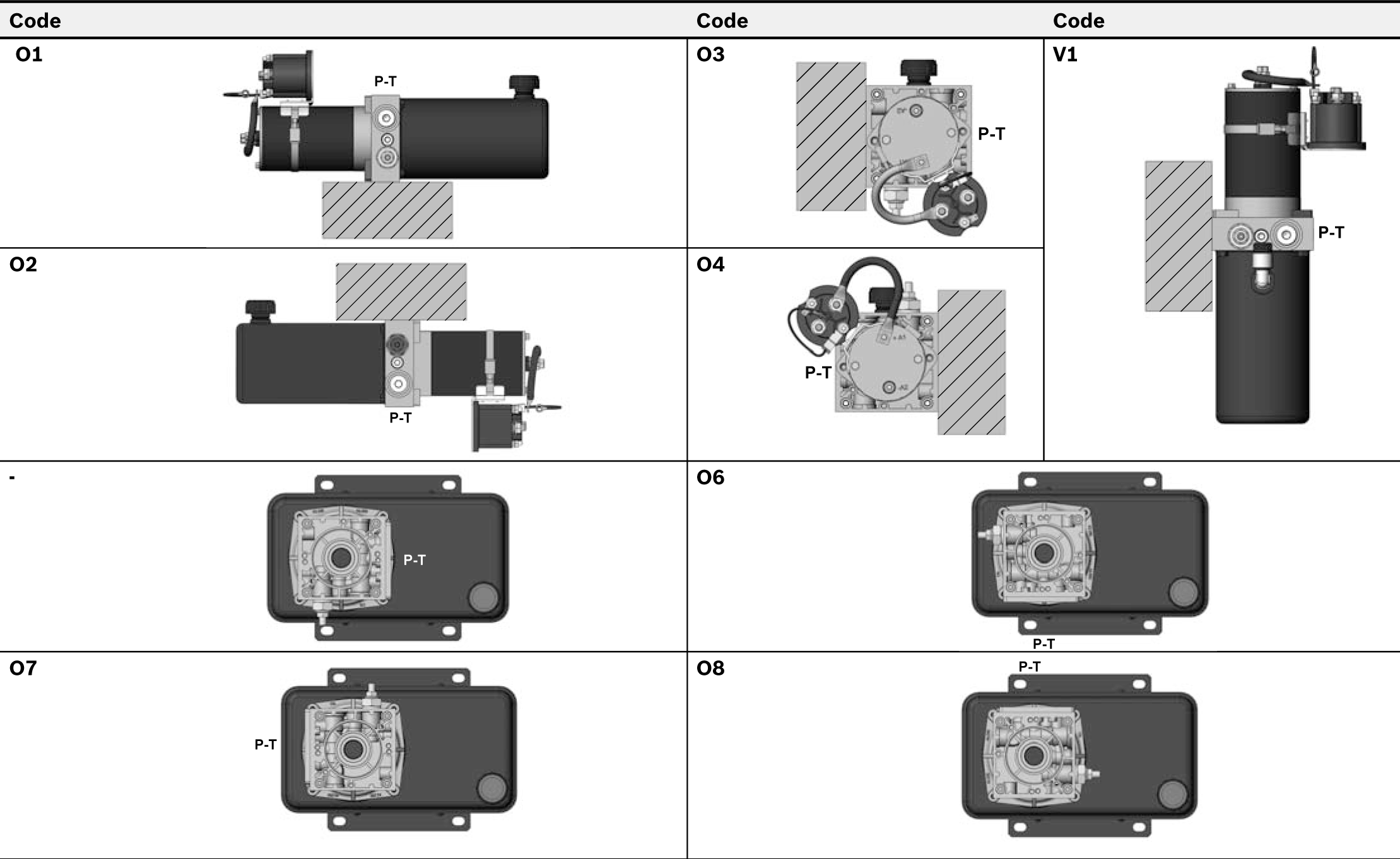
RE18306-01-114

Relay Position for D.C. Motors

RE18306-01-115

Oil Cap Position for V1 only

RE18306-01-116

Support for Manifold ME - MR Series

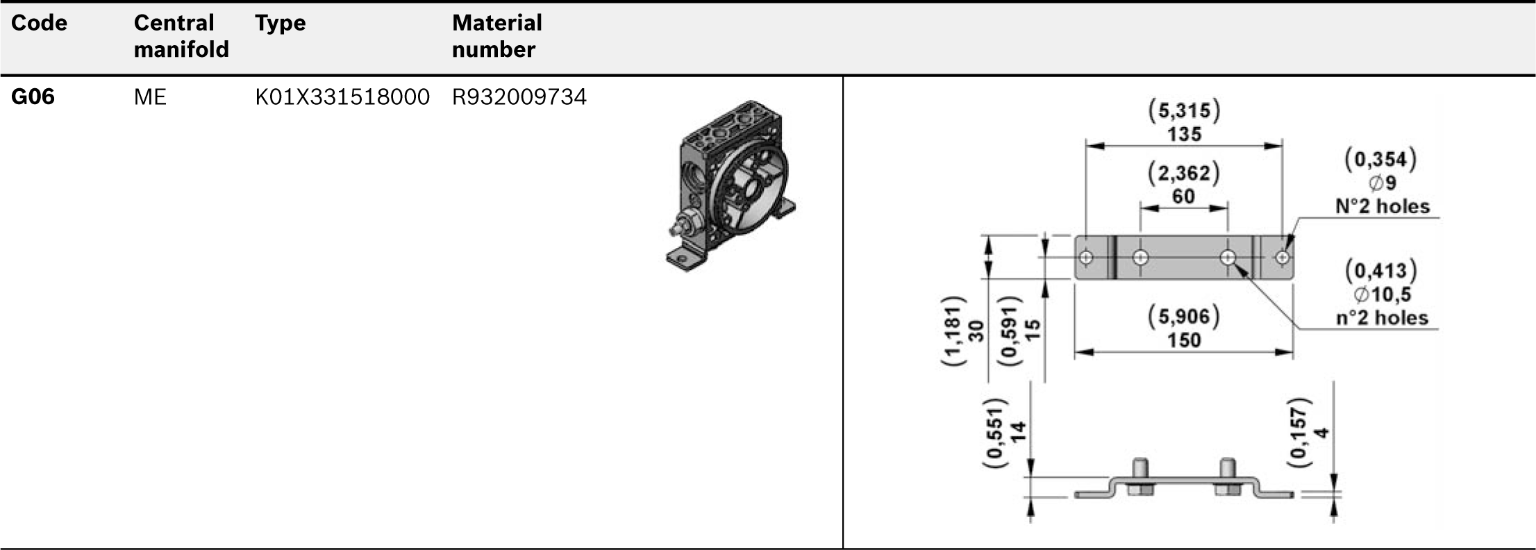
RE18306-01-117

Support for Manifold Code A16

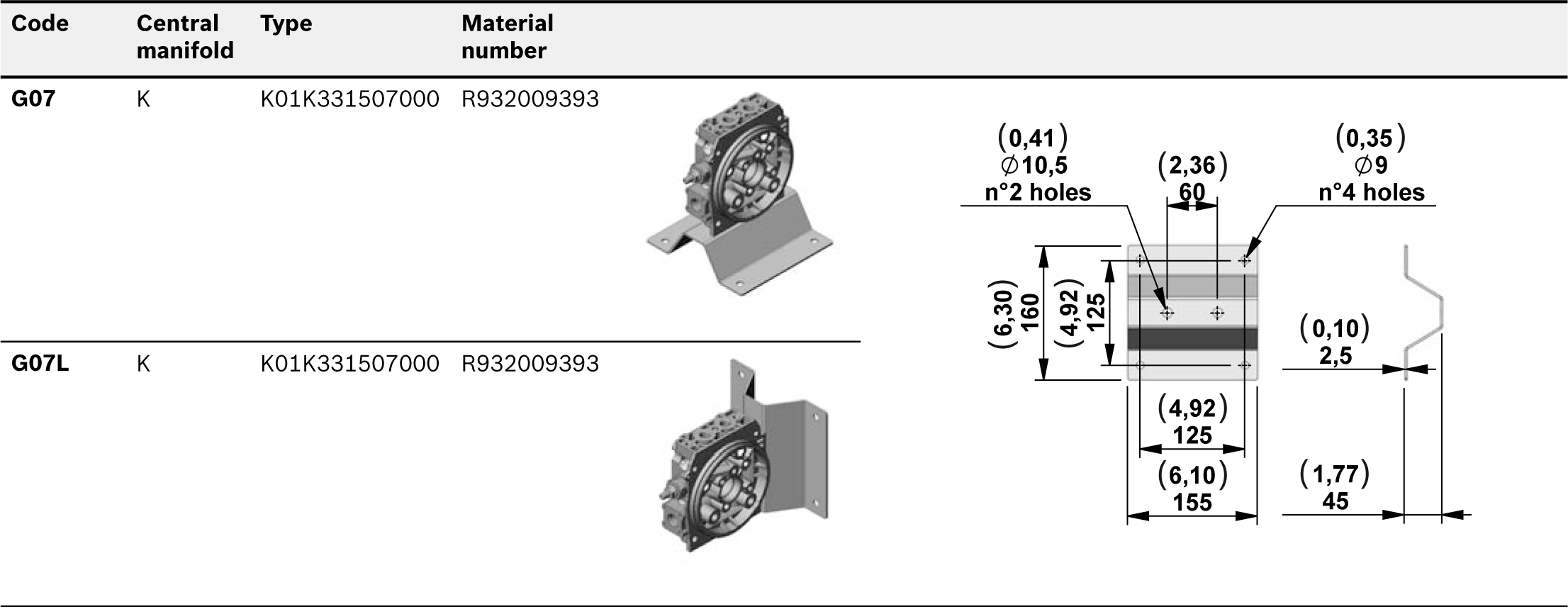
RE18306-01-118

Space Modular Block

RE18306-01-119

RE18306-01-120

These modular blocks have been designed to have the ability to be assembled as a stack to allow clearence between flanges and motors of different sizes and types. Each block includes 2 OR 3056 gaskets.
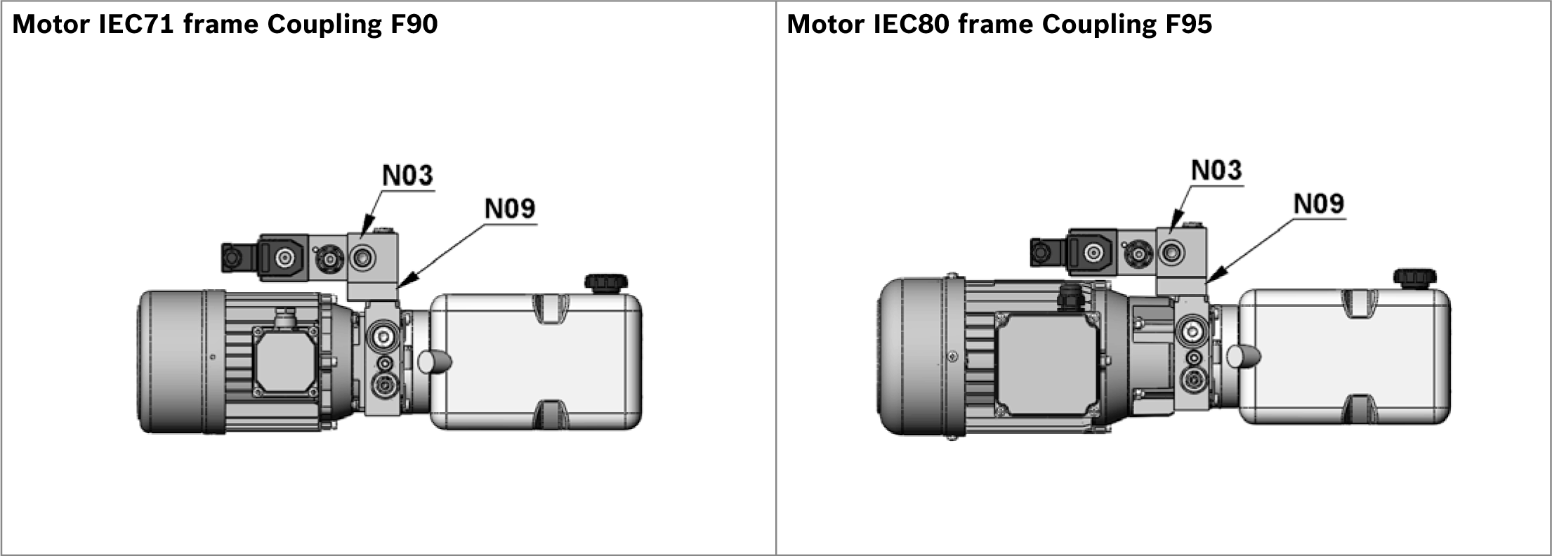

RE18306-01-121
Code
Description
Max working pressure bar (psi)
Max flow l/min (gpm)
Type
Material number
N09
Space modular block
300 (4351)
40 (10,57)
G386010000
R932001058

90° modular block allowing horizontal mounting (motor side)
RE18306-01-122

RE18306-01-123

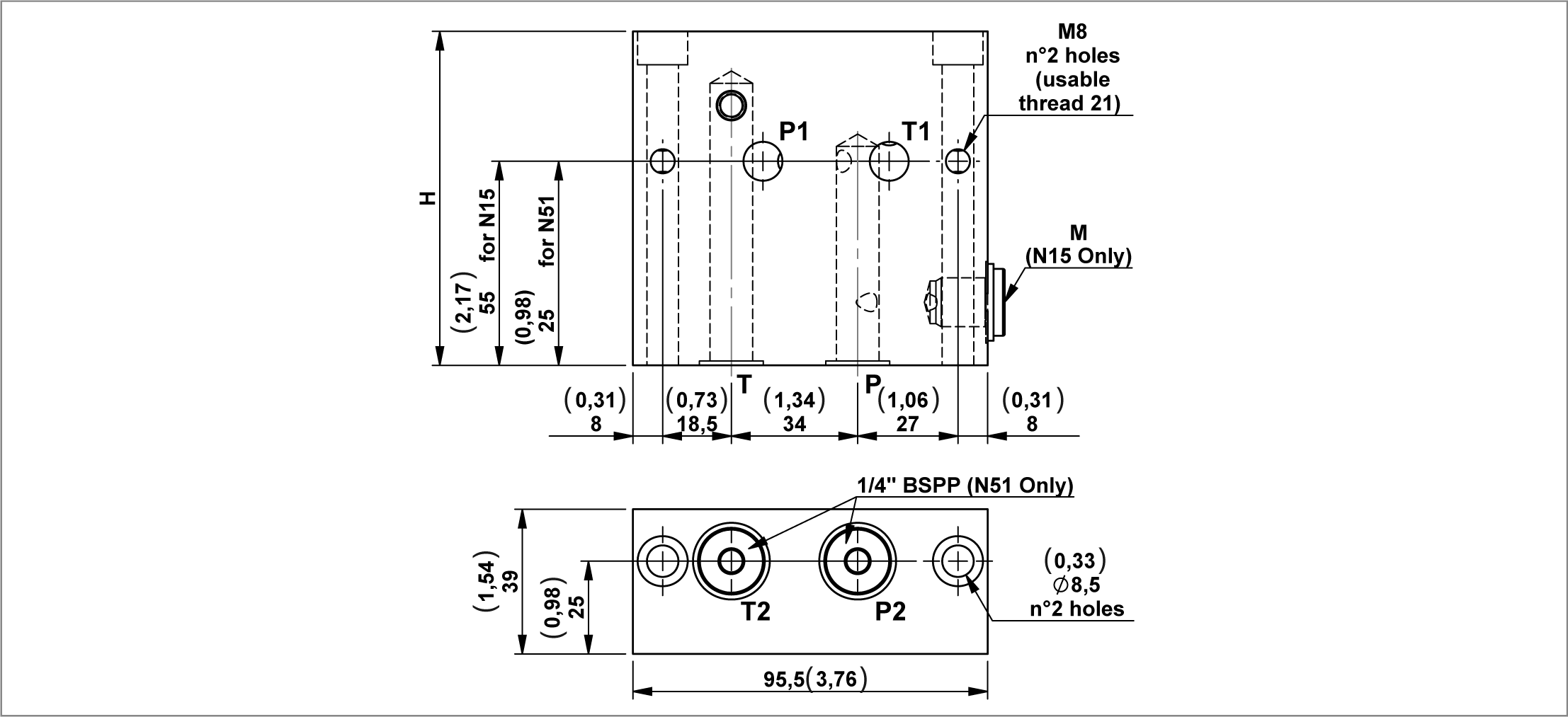
A modular block that is able to turn the standard assembling of 90°, in order to place other manifold blocks over the motor.

The “N15” block has a 1/4” BSPP port for Pressure Gauge. Each block includes 2 OR 2056 gaskets.


RE18306-01-124
Code
Description
Max working pressure bar (psi)
Max flow l/min (gpm)
Type
Material number
N15
90° modular block allowing horizontal mounting (motor side) H=90
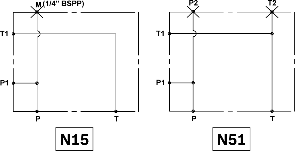
300 (4351)
35 (9,25)
G386014000
R932001087
N51
90° modular block allowing horizontal mounting (motor side) H=60
300 (4351)
35 (9,25)
G386050000
R932001146

90° modular block allowing horizontal mounting (tank side)

RE18306-01-125

RE18306-01-126

A modular block that is able to turn the standard assembling of 90°, in order to place other blocks over the tank.

The blocks have a 1/4” BSPP port for Pressure Gauge. Each block includes 2 OR 2056 gaskets.


RE18306-01-127
Code
Description
Max working pressure bar (psi)
Max flow l/min (gpm)
Type
Material number
N76
90° modular block allowing horizontal mounting (tank side) H=90
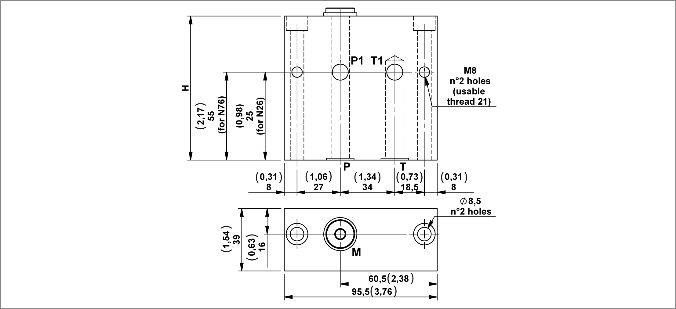
300 (4351)
35 (9,25)
G386075000
R932001153
N26
90° modular block allowing horizontal mounting (tank side) H=60
300 (4351)
35 (9,25)
G386025000
R932001100

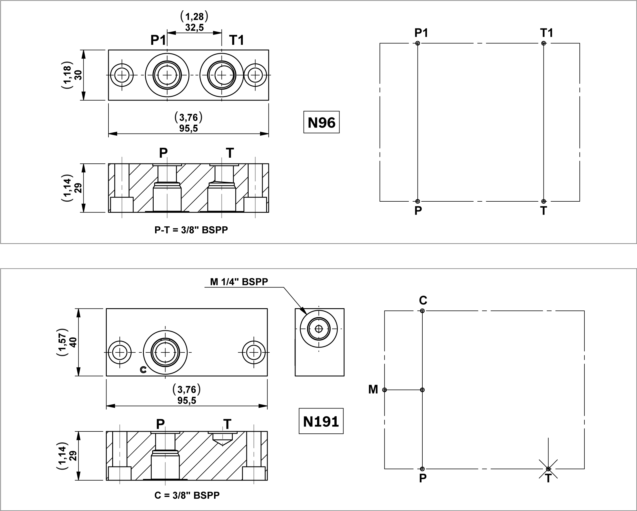
Modular blocks with threaded ports

RE18306-01-128

Modular blocks with exit 3/8” BSPP.

Each block includes 2 OR 2056 gaskets.


Code
Description
Max working pressure bar (psi)
Max flow l/min (gpm)
Type
Material number
N96
Modular block with threaded ports
300 (4351)
35 (9,25)
G386095000
R932001173
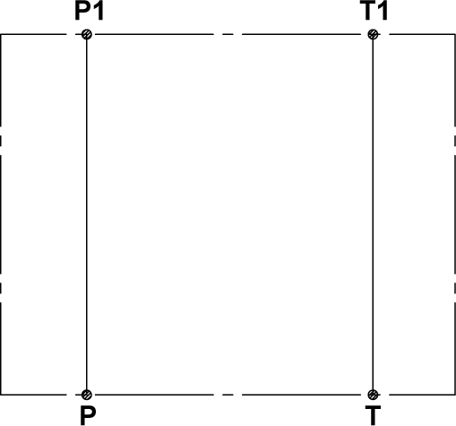
N191
Modular block with threaded ports
300 (4351)
35 (9,25)
G386191000
R932001284

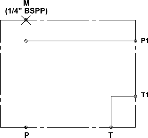
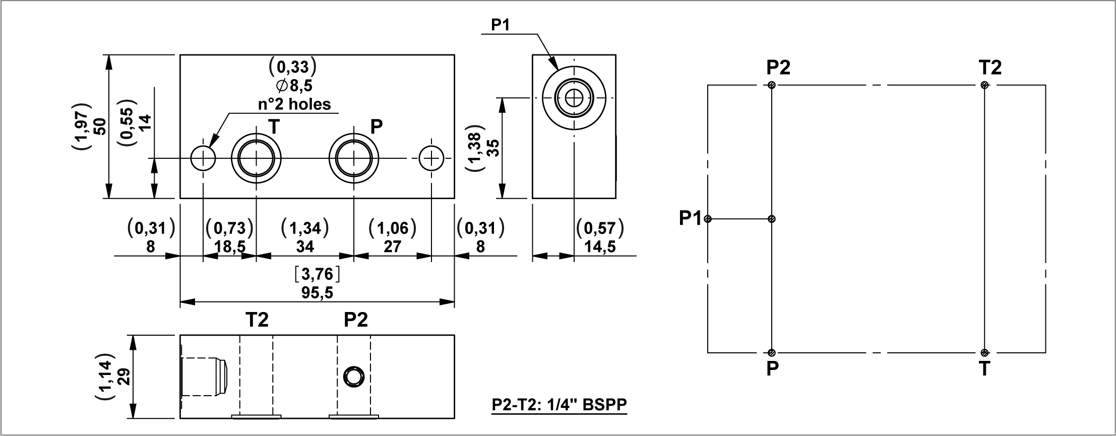
Modular spacer block with extra “P1” port
RE18306-01-129

A modular block with an extra port.

Each block includes 2 OR 2056 gaskets.


Code
Description
Max working pressure bar (psi)
Max flow l/min (gpm)
Type
Material number
N46-14
Modular spacer block with extra "P1" port 1/4" BSPP
300 (4351)
20 (5,28)
G386045000
R932001142
N46-38
Modular spacer block with extra "P1" port 3/8" BSPP
300 (4351)
20 (5,28)
1386000053
R932009506

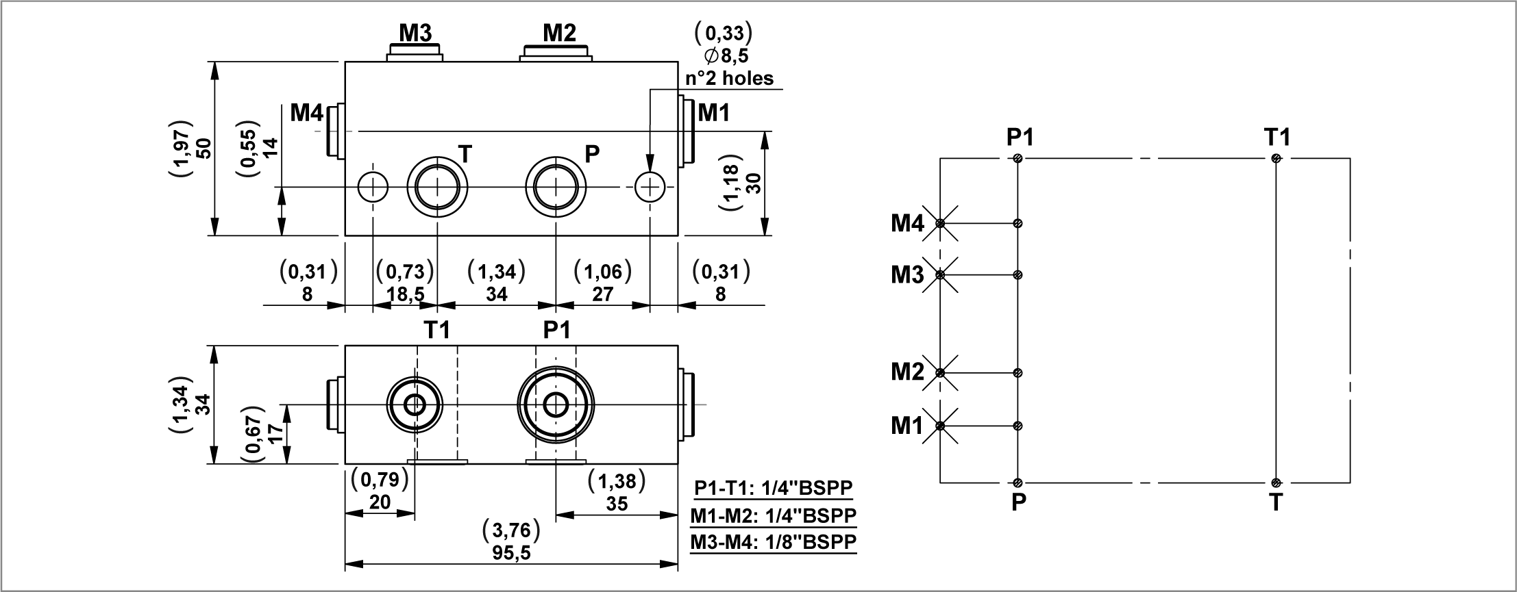
Modular spacer block with two 1/8” BSPP and two 1/4” BSPP ports
RE18306-01-130

A modular block with 4 extra ports.

Each block includes 2 OR 2056 gaskets.


Code
Description
Max working pressure bar (psi)
Max flow l/min (gpm)
Type
Material number
N128
Modular spacer plock with two 1/8" BSPP ports and two 1/4" BSPP ports
300 (4351)
35 (9,25)
G386128000
R932001241

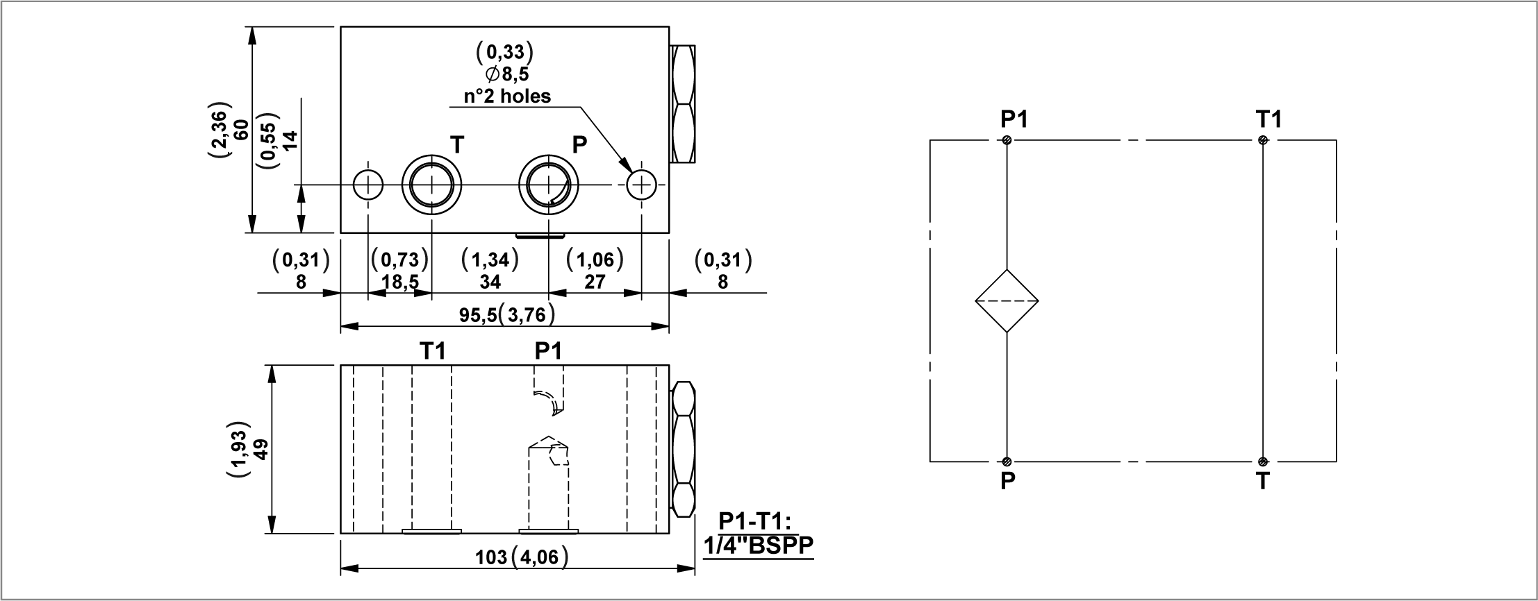
Modular block with filter on pressure line
RE18306-01-131

A modular block with a filter on the pressure line. This is recommended for applications where valve may be subjected to contamination. Each block includes 2 OR 2056 gaskets.


Code
Description
Max working pressure bar (psi)
Max flow l/min (gpm)
Type
Material number
N39-25
Modular block with filter (25 micron) on pressure line
230 (3336)
10 (2,64)
G386038010
R932001123
N39-60
Modular block with filter (60 micron) on pressure line
230 (3336)
10 (2,64)
G386038020
R932001124

Modular block with filter on the return line
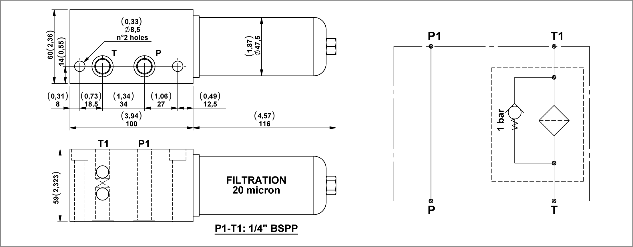
RE18306-01-132

A modular block with filter on return line. This is recommended for applications where valves may be subjected to contamination. Each block includes 2 OR 2056 gaskets.

By-pass valve set at a pressure of 1 bar.


Code
Description
Max working pressure bar (psi)
Max flow l/min (gpm)
Type
Material number
N116
Modular block with filter on the return line (20 micron)
6 (87)
20 (5,28)
G386116010
R932001214

Modular block for CETOP 3 (2143) configuration valves
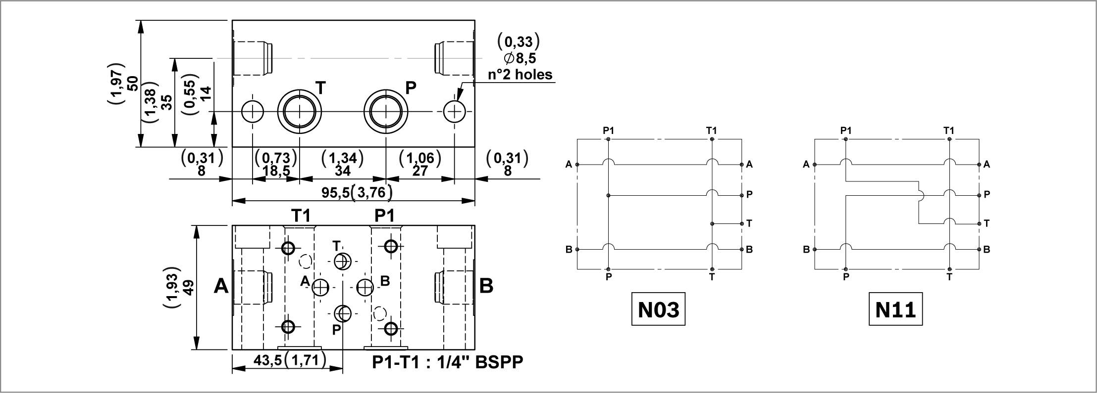
RE18306-01-133

Modular blocks for CETOP 3 (2143) electrovalves for parallel or series circuits.

Each block includes 2 OR 2056 gaskets.


Code
Description
Max working pressure bar (psi)
Max flow l/min (gpm)
Type
Material number
N03-14
Modular block for CETOP3 (2143) configuration valves with A-B 1/4" BSPP (parallel circuit)
300 (4351)
40 (10,57)
G386002010
R932001010
N03-38
Modular block for CETOP3 (2143) configuration valves with A-B 3/8" BSPP (parallel circuit)
300 (4351)
40 (10,57)
G386002020
R932001011
N11-14
Modular block for CETOP3 (2143) configuration valves with A-B 1/4" BSPP (series circuit)
300 (4351)
40 (10,57)
G386009010
R932001054
N11-38
Modular block for CETOP3 (2143) configuration valves with A-B 3/8" BSPP (series circuit)
300 (4351)
40 (10,57)
G386009020
R932001056

Modular block for CETOP 3 (2143) configuration valves
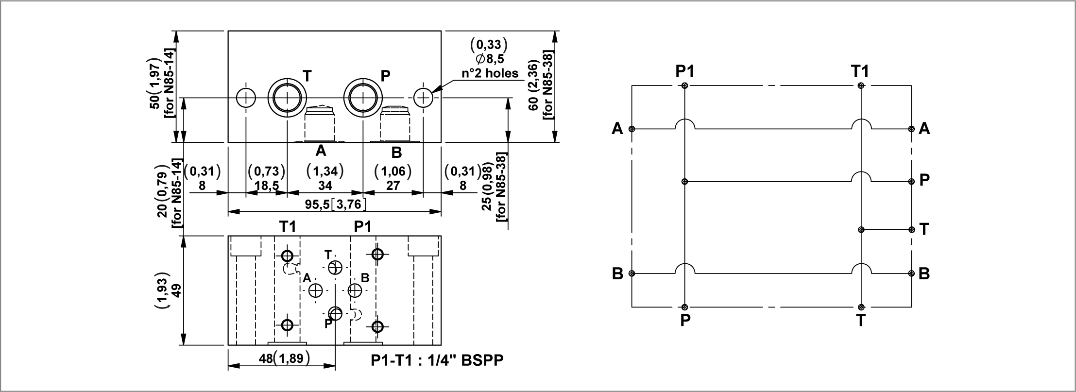
RE18306-01-134

A modular block that is for CETOP 3 (2143) electrovalves for a parallel circuit with ports on the oppsite side of the valve.

Each block includes 2 OR 2056 gaskets.


Code
Description
Max working pressure bar (psi)
Max flow l/min (gpm)
Type
Material number
N85-14
Modular block for CETOP3 (2143) configuration valves with A-B 1/4" BSPP (parallel circuit)
300 (4351)
40 (10,57)
G386084010
R932001158
N85-38
Modular block for CETOP3 (2143) configuration valves with A-B 3/8" BSPP (parallel circuit)
300 (4351)
40 (10,57)
G386084020
R932001159

Modular block for CETOP 3 (2143) configuration valves with side ports
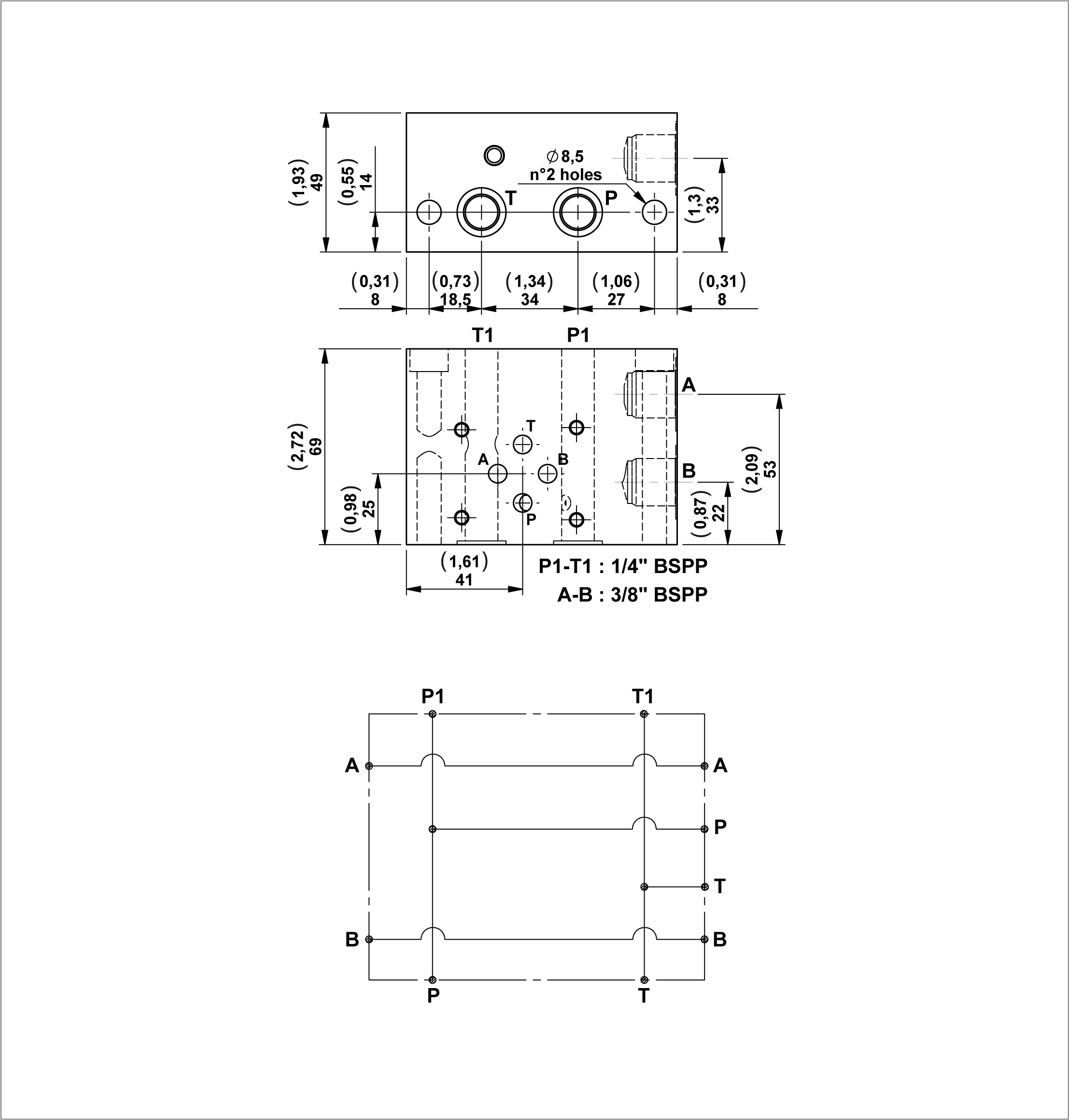
RE18306-01-135

A modular block that is for CETOP 3 (2143) electrovalves for parallel circuit with side device ports on one face.

Each block includes 2 OR 2056 gaskets.


Code
Description
Max working pressure bar (psi)
Max flow l/min (gpm)
Type
Material number
N142
Modular block for CETOP 3 (2143) confuguration valves with side ports
300 (4351)
40 (10,57)
G386142000
R932001252

Modular block with poppet type P.O. check valves for CETOP 3 (2143) configuration valves (parallel circuit)
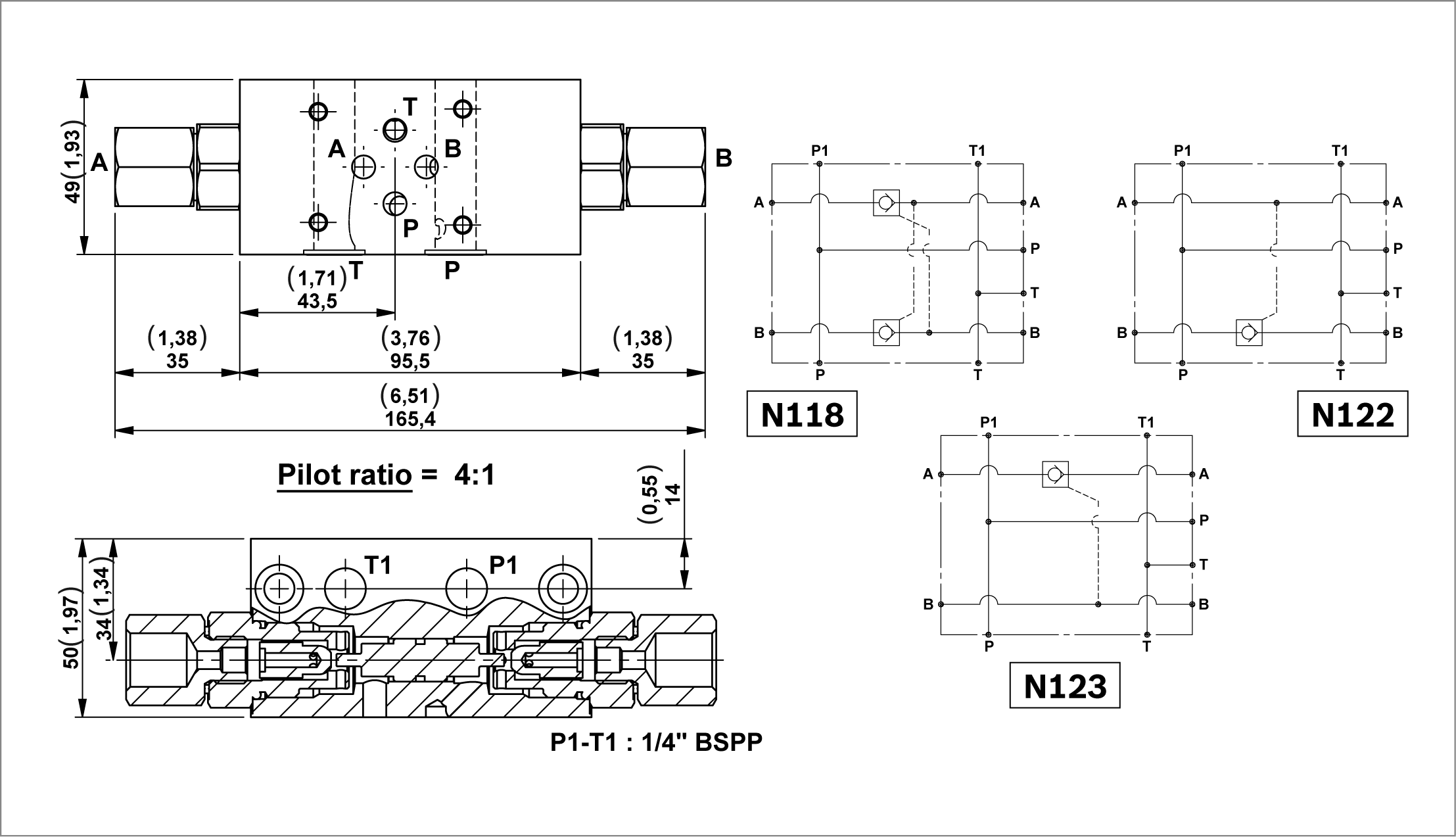
RE18306-01-136

A selection of modular block with P.O. check valves for block CETOP 3 (2143) electrovalves.

Each block includes 2 OR 2056 gaskets.

Possibility to have an OR gasket on the piloting piston for application with low flow.


Code
Description
Max working pressure bar (psi)
Max flow l/min (gpm)
Type
Material number
N118-38
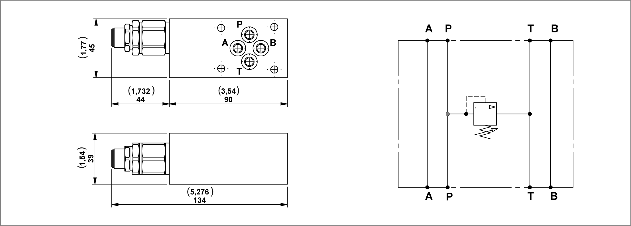
Modular block with poppet type P.O. check valves on A-B for CETOP 3 (2143) configuration valves (without O-ring on pilot piston and A-B 3/8" BSPP)
300 (4351)
20 (5,28)
G386118A02
R932001217
N118G-38
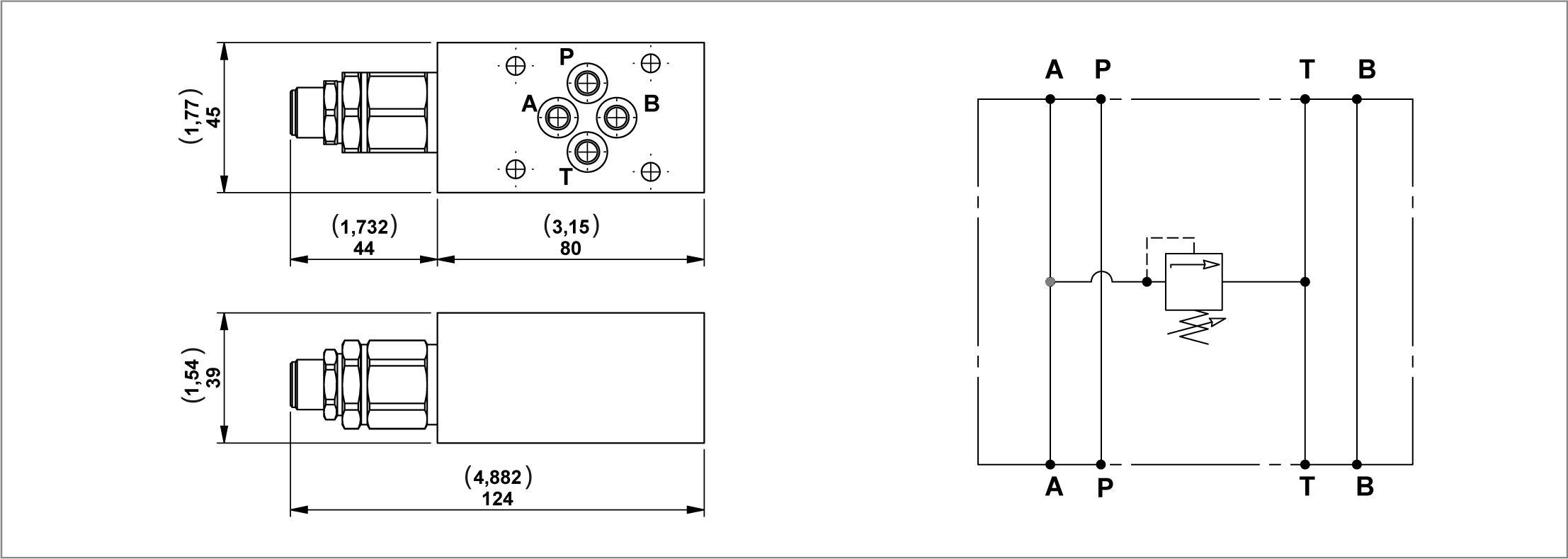
Modular block with poppet type P.O. check valves on A-B for CETOP 3 (2143) configuration valves (with O-ring on pilot piston and A-B 3/8" BSPP)
300 (4351)
20 (5,28)
G386118B02
R932001222
N118-14
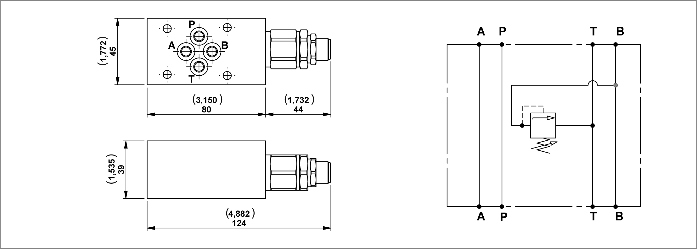
Modular block with poppet type P.O. check valves on A-B for CETOP 3 (2143) configuration valves (without O-ring on pilot piston and A-B 1/4" BSPP)
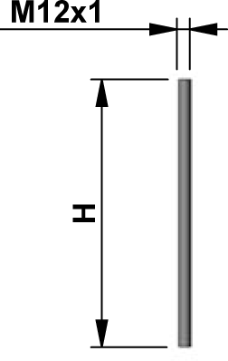
300 (4351)
20 (5,28)
G386118A03
R932001218
N118G
14 Modular block with poppet type P.O. check valves on A-B for CETOP 3 (2143) configuration valves (with O-ring on pilot piston and A-B 1/4" BSPP)
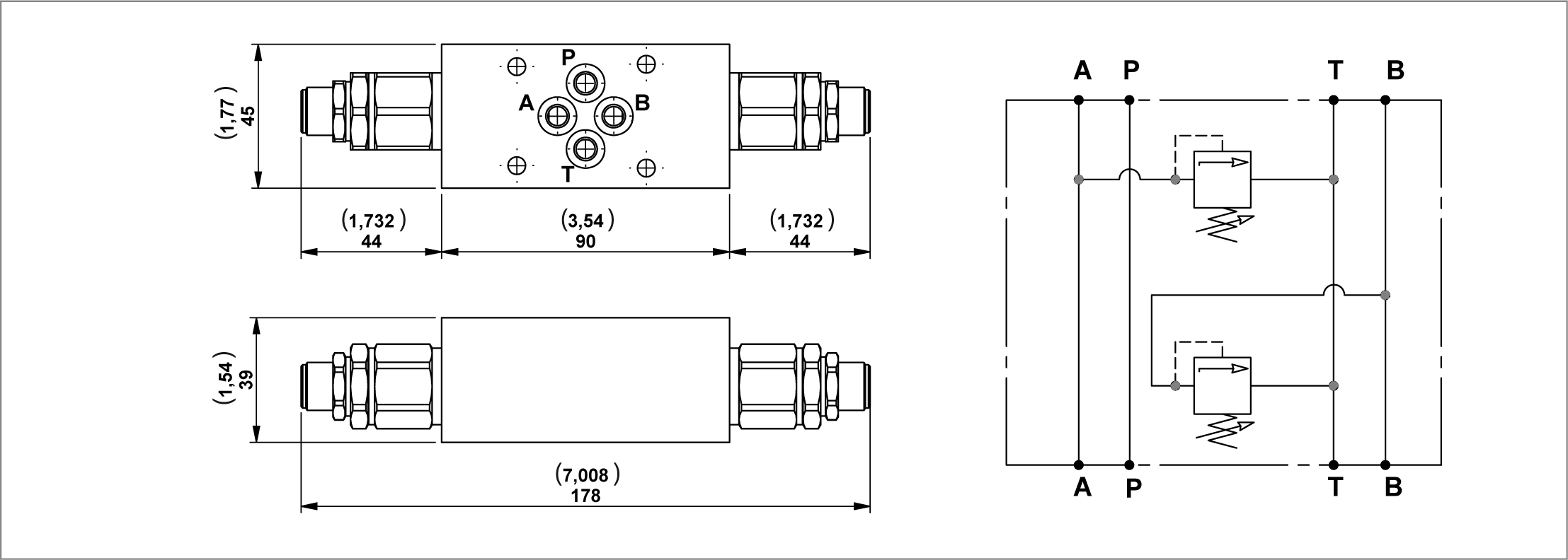
300 (4351)
20 (5,28)
G386118B03
R932001223
N122-38
Modular block with poppet type P.O. check valve on B for CETOP 3 (2143) configuration valves (without O-ring on pilot piston and A-B 3/8" BSPP)
300 (4351)
20 (5,28)
G386122A02
R932001233
N122-14
Modular block with poppet type P.O. check valve on B for CETOP 3 (2143) configuration valves (without O-ring on pilot piston and A-B 1/4" BSPP)
300 (4351)
20 (5,28)
G386122A01
R932001232
N123-38
Modular block with poppet type P.O. check valves on A for CETOP 3 (2143) configuration valves (without O-ring on pilot piston and A-B 3/8" BSPP)
300 (4351)
20 (5,28)
G386123A02
R932001237
N123-14
Modular block with poppet type P.O. check valves on A for CETOP 3 (2143) configuration valves (without O-ring on pilot piston and A-B 1/4" BSPP)
300 (4351)
20 (5,28)
G386123A01
R932001236

Sandwich blocks with poppet type “VMD1“ relief valves for CETOP 3 (2143) configuration valves

RE18306-01-137

Each block includes 4 OR 108 gaskets.


Code
Description
Max working pressure bar (psi)
Max flow l/min (gpm)
Type
Material number
N99-10
Sandwich block with poppet type "VMD1" relief valve P in T (25-120 bar) for CETOP3 (2143) configuration valves
300 (4351)
25 (6,60)
G386098A81A
R930071372
N99-20
Sandwich block with poppet type "VMD1" relief valve P in T (40-200 bar) for CETOP3 (2143) configuration valves
300 (4351)
25 (6,60)
G386098A82A
R930071373
N99-35
Sandwich block with poppet type "VMD1" relief valve P in T (200-350 bar) for CETOP3 (2143) configuration valves
300 (4351)
25 (6,60)
G386098A83A
R930071376

Sandwich blocks with poppet type “VMD1“ relief valves for CETOP 3 (2143) configuration valves

RE18306-01-138

Each block includes 4 OR 108 gaskets.


Code
Description
Max working pressure bar (psi)
Max flow l/min (gpm)
Type
Material number
N100-10
Sandwich block with poppet type "VMD1" relief valve A in T (25-120 bar) for CETOP3 (2143) configuration valves
300 (4351)
25 (6,60)
G386099A81A
R930071377
N100-20
Sandwich block with poppet type "VMD1" relief valve A in T (40-200 bar) for CETOP3 (2143) configuration valves
300 (4351)
25 (6,60)
G386099A82A
R930071378
N100-35
Sandwich block with poppet type "VMD1" relief valve A in T (200-350 bar) for CETOP3 (2143) configuration valves
300 (4351)
25 (6,60)
G386099A83A
R930071379

Sandwich blocks with poppet type “VMD1“ relief valves for CETOP 3 (2143) configuration valves

RE18306-01-139

Each block includes 4 OR 108 gaskets.


Code
Description
Max working pressure bar (psi)
Max flow l/min (gpm)
Type
Material number
N101-10
Sandwich block with poppet type "VMD1" relief valve B in T (25-120 bar) for CETOP3 (2143) configuration valves
300 (4351)
25 (6,60)
G386101A81A
R930071380
N101-20
Sandwich block with poppet type "VMD1" relief valve B in T (40-200 bar) for CETOP3 (2143) configuration valves
300 (4351)
25 (6,60)
G386101A82A
R930071381
N101-35
Sandwich block with poppet type "VMD1" relief valve B in T (200-350 bar) for CETOP3 (2143) configuration valves
300 (4351)
25 (6,60)
G386101A83A
R930071382

Sandwich blocks with poppet type “VMD1“ relief valves for CETOP 3 (2143) configuration valves

RE18306-01-140

Each block includes 4 OR 108 gaskets.


Code
Description
Max working pressure bar (psi)
Max flow l/min (gpm)
Type
Material number
N102-10
Sandwich block with poppet type "VMD1" relief valves A-B in T (25-120 bar) for CETOP3 (2143) configuration valves
300 (4351)
25 (6,60)
G386102A81A
R930071383
N102-20
Sandwich block with poppet type "VMD1" relief valves A-B in T (40-200 bar) for CETOP3 (2143) configuration valves
300 (4351)
25 (6,60)
G386102A82A
R930071384
N102-35
Sandwich block with poppet type "VMD1" relief valves A-B in T (200-350 bar) for CETOP3 (2143) configuration valves
300 (4351)
25 (6,60)
G386102A83A
R930071385

Sandwich blocks with “ST-CU-06” adjustable flow control valves for CETOP 3 (2143) configuration valves
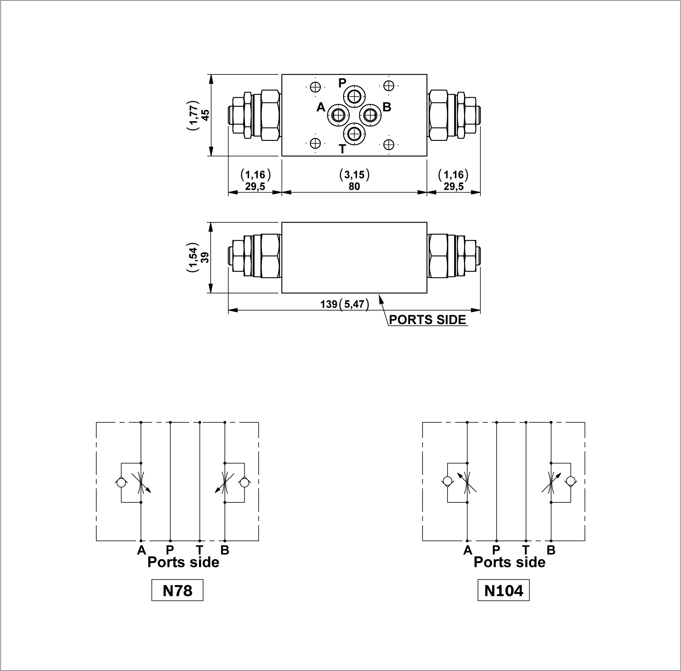
RE18306-01-141

Each block includes 4 OR 108 gaskets.


Code
Description
Max working pressure bar (psi)
Max flow l/min (gpm)
Type
Material number
N78
Sandwich blocks with ST-CU-06 adjustable flow control valves (that working on the return to the tank of the A and B line) for CETOP 3 (2143) configuration valves
300 (4351)
25 (6,60)
G386077A81
R932001156
N104
Sandwich blocks with ST-CU-06 adjustable flow control valves (that working on the delivery of the A and B line)
300 (4351)
25 (6,60)
G386104A80
R932001205

Sandwich blocks with “ST-CU-06” adjustable flow control valves for CETOP 3 (2143) configuration valves
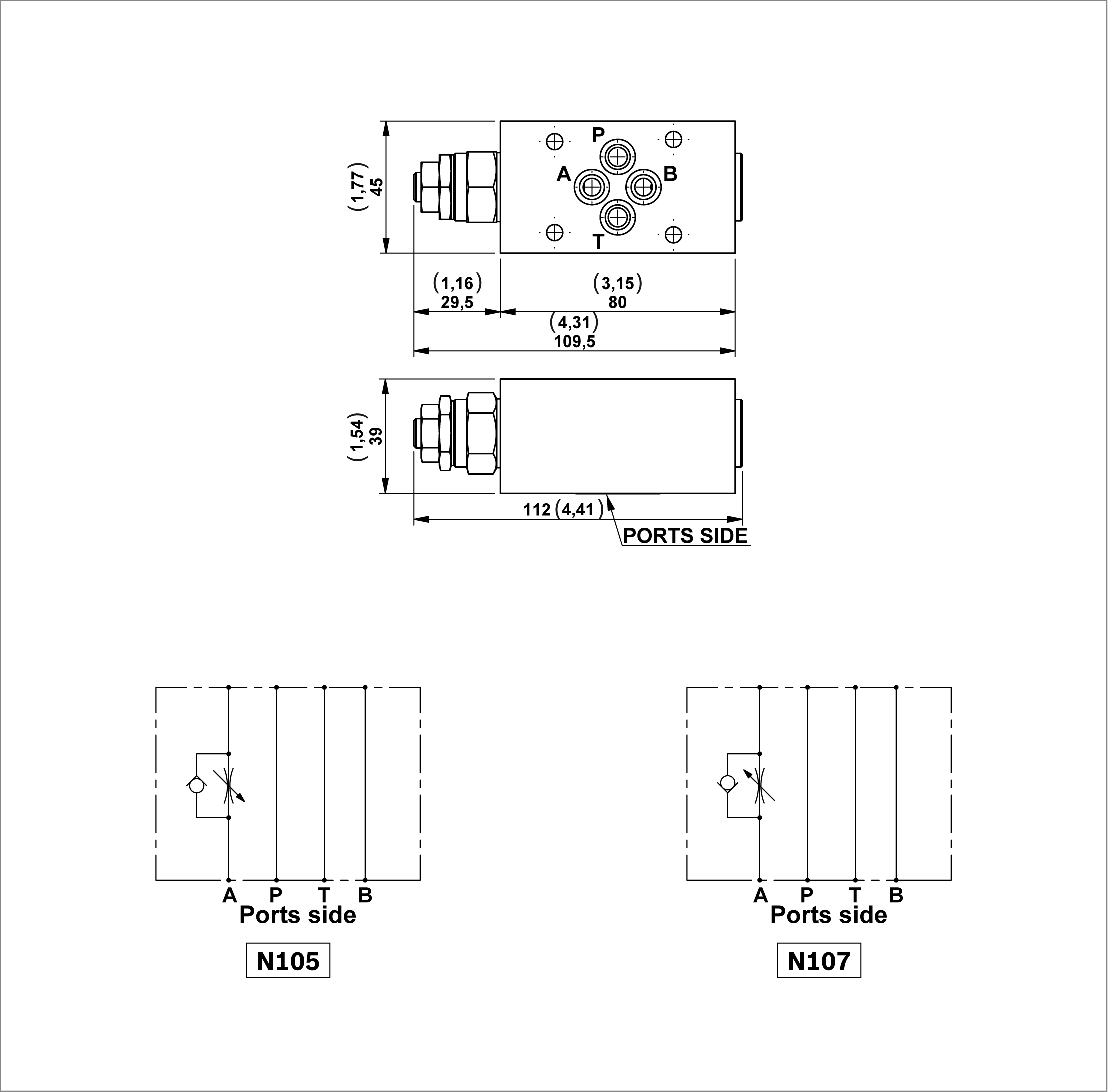
RE18306-01-142

Each block includes 4 OR 108 gaskets.


Code
Description
Max working pressure bar (psi)
Max flow l/min (gpm)
Type
Material number
N105
Sandwich blocks with ST-CU-06 adjustable flow control valves (that working on the return to the tank of the A line) for CETOP 3 (2143) configuration valves
300 (4351)
25 (6,60)
G386105A81
R932000183
N107
Sandwich blocks with ST-CU-06 adjustable flow control valves (that working on the delivery of the A line) for CETOP 3 (2143) configuration valves
300 (4351)
25 (6,60)
G386107A80
R932001211

Sandwich blocks with “ST-CU-06” adjustable flow control valves for CETOP 3 (2143) configuration valves
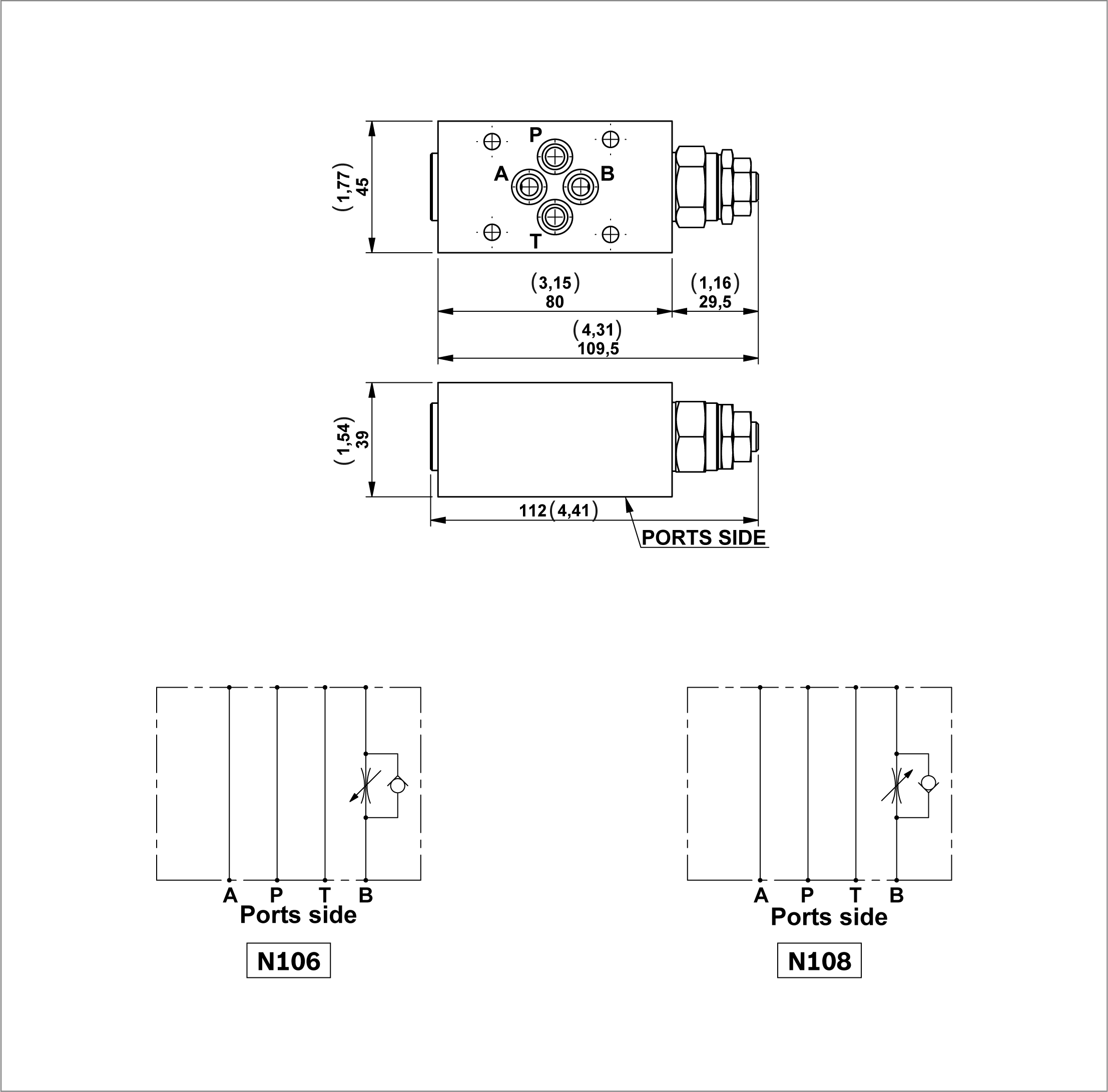
RE18306-01-143

Each block includes 4 OR 108 gaskets.


Code
Description
Max working pressure bar (psi)
Max flow l/min (gpm)
Type
Material number
N106
Sandwich blocks with ST-CU-06 adjustable flow control valves (that working on the return to the tank of the B line) for CETOP 3 (2143) configuration valves
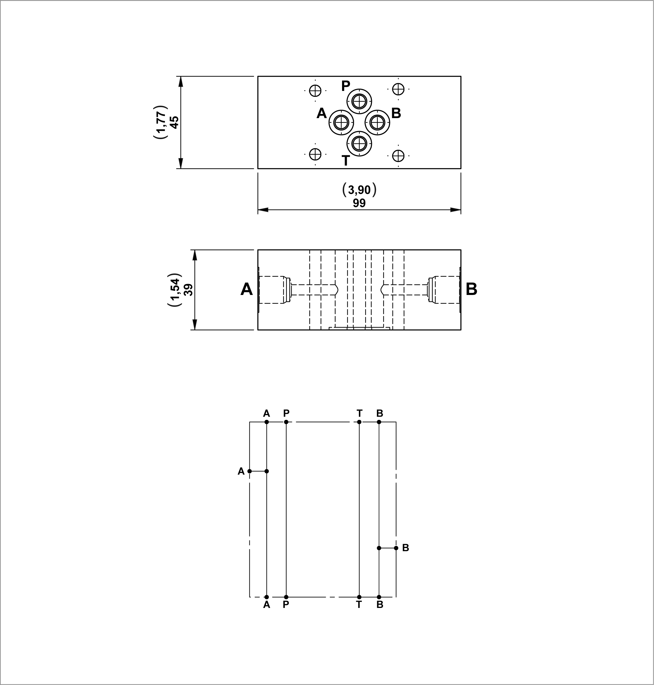
300 (4351)
25 (6,60)
G386106A81
R932000184
N108
Sandwich blocks with ST-CU-06 adjustable flow control valves (that working on the delivery of the B line)
300 (4351)
25 (6,60)
G386108A80
R932001212

Sandwich block with ports on “A” and “B” line for CETOP 3 (2143) configuration valves
RE18306-01-144

Each block includes 2 OR 2056 gaskets.


Code
Description
Max working pressure bar (psi)
Max flow l/min (gpm)
Type
Material number
N19-14
Sandwich block with 1/4" BSPP ports on A and B line for CETOP3 (2143) configuration valves
300 (4351)
25 (6,60)
G386018010
R932001091

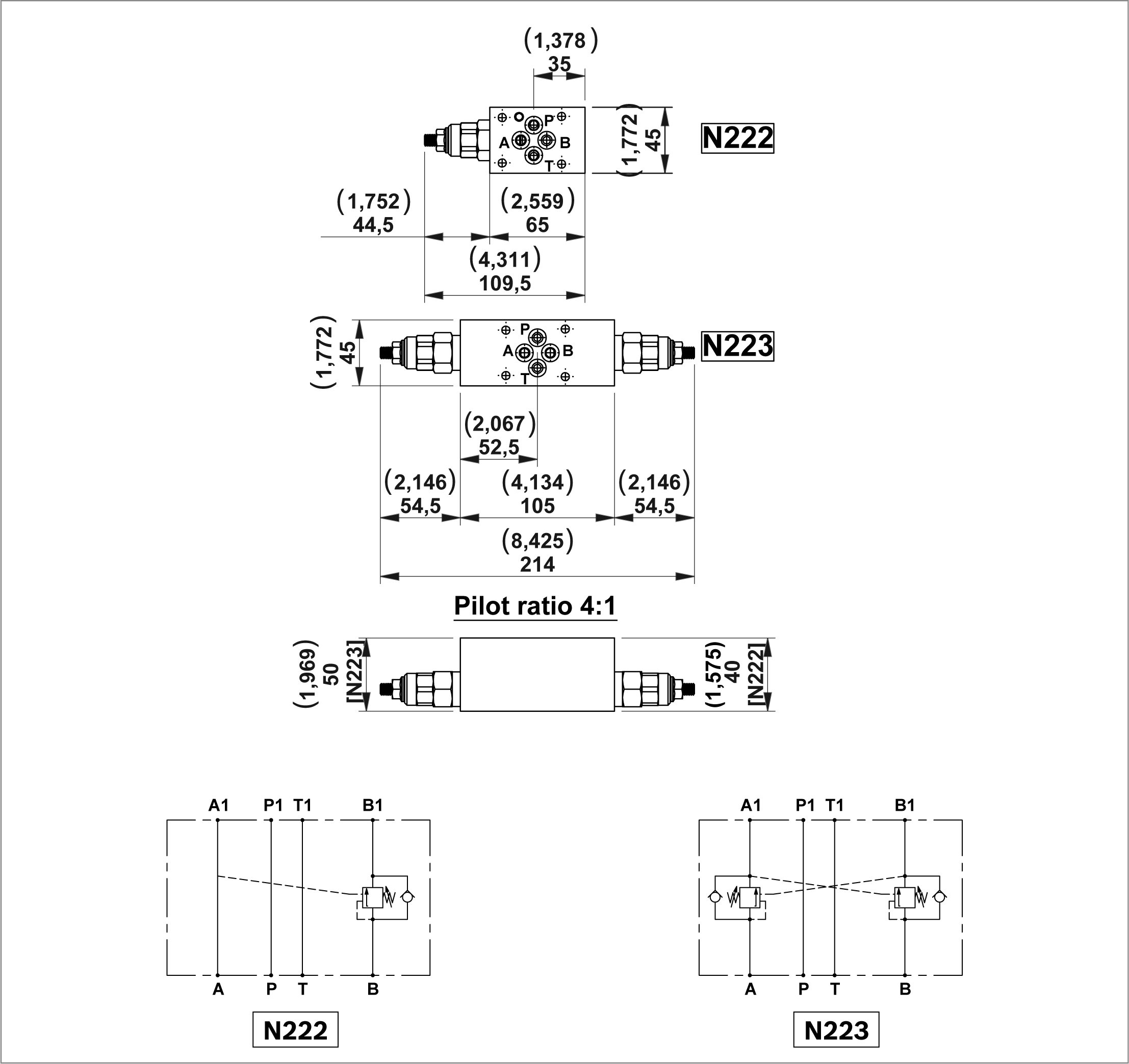
Sandwich blocks with overcenter valves for CETOP 3 (2143) configuration valves

RE18306-01-145

Each block includes 4 OR 108 gaskets.


Code
Description
Max working pressure bar (psi)
Max flow l/min (gpm)
Type
Material number
N222.20
Sandwich block with Overcentre valve VBSN-08AA (100-210 bar) on B line for CETOP3
300 (4351)
30 (7,93)
G386222002
R932001326
N222.35
Sandwich block with Overcentre valve VBSN-08AA (200-350 bar) on B line for CETOP3
300 (4351)
30 (7,93)
G386222003
R932001327
N223.20
Sandwich block with Overcentre valves VBSN-08AA (100-210 bar) on A and B line for CETOP3
300 (4351)
30 (7,93)
G386223002
R932001329
N223.35
Sandwich block with Overcentre valves VBSN-08AA (200-350 bar) on A and B line for CETOP3
300 (4351)
30 (7,93)
G386223003
R932001330

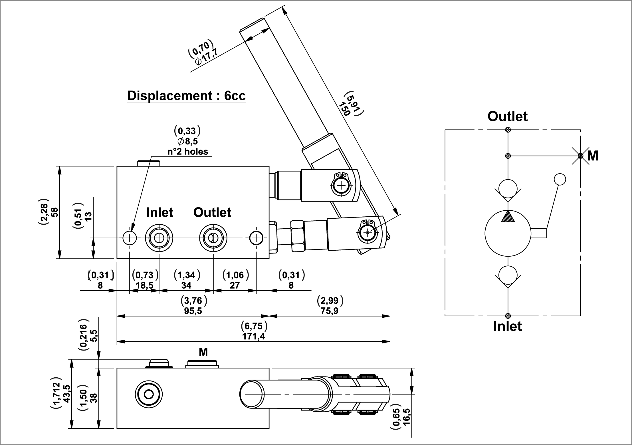
Modular hand pump manifold block

RE18306-01-146

A single acting hand pump usually used for emergency.

Each block includes 5 OR 2050 gaskets.


Code
Description
Max working pressure bar (psi)
Max flow l/min (gpm)
Type
Material number
N22
Modular hand pump manifold block
350 (5076)
-
G386021A10
R930067575

Lever Kit

RE18306-01-147
Description
Type
Material number
Lever L= 450
K250133000
R932002452
Lever L= 280
K2501S1058
R932002407

CETOP 2143 (Ø6mm (0,24inch) ) Solenoid Valves
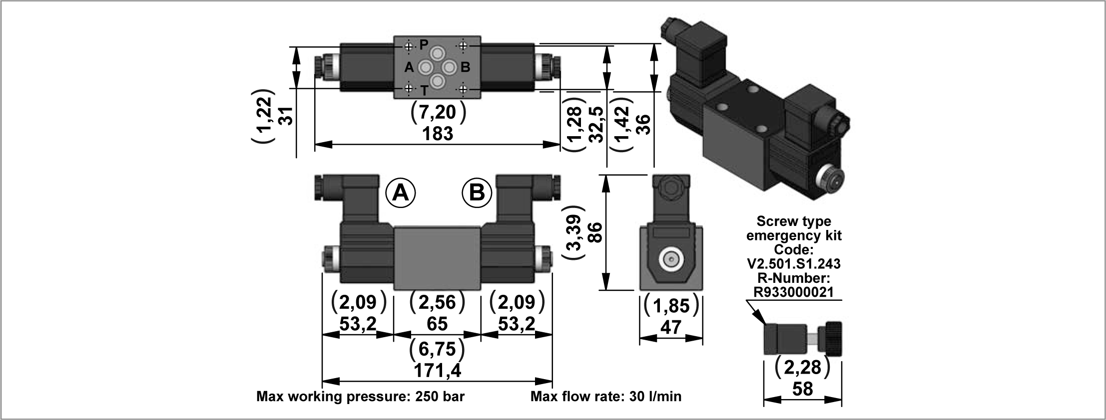
RE18306-01-148
Code
Description
Max working pressure bar (psi)
Max flow l/min (gpm)
Material number
Diagram
E02Z-OB
CETOP3 solenoid valve 12V D.C.
250 (3626)
30 (7,92)
R933004275
E02Z-OC
CETOP3 solenoid valve 24V D.C.
250 (3626)
30 (7,92)
R933004277
E02Z-OV
CETOP3 solenoid valve 24V RAC
250 (3626)
30 (7,92)
R933004279
E02Z-OZ
CETOP3 solenoid valve 220V RAC
250 (3626)
30 (7,92)
R933004281
E06Z-OB
CETOP3 solenoid valve 12V D.C.
250 (3626)
30 (7,92)
R933004096
E06Z-OC
CETOP3 solenoid valve 24V D.C.
250 (3626)
30 (7,92)
R933004098
E06Z-OD
CETOP3 solenoid valve 48V D.C.
250 (3626)
30 (7,92)
R933007830
E06Z-OV
CETOP3 solenoid valve 24V RAC
250 (3626)
30 (7,92)
R933004102
E06Z-OW
CETOP3 solenoid valve 110V RAC
250 (3626)
30 (7,92)
R933004103
E06Z-OZ
CETOP3 solenoid valve 220V RAC
250 (3626)
30 (7,92)
R933004104
E07Z-OB
CETOP3 solenoid valve 12V D.C.
250 (3626)
30 (7,92)
R933004131
E07Z-OC
CETOP3 solenoid valve 24V D.C.
250 (3626)
30 (7,92)
R933004133
E07Z-OD
CETOP3 solenoid valve 48V D.C.
250 (3626)
30 (7,92)
R933004135
E07Z-OV
CETOP3 solenoid valve 24V RAC
250 (3626)
30 (7,92)
R933004136
E07Z-OW
CETOP3 solenoid valve 110V RAC
250 (3626)
30 (7,92)
R933004137
E07Z-OZ
CETOP3 solenoid valve 220V RAC
250 (3626)
30 (7,92)
R933004138
E08Z-OB
CETOP3 solenoid valve 12V D.C.
250 (3626)
30 (7,92)
R933004191
E08Z-OC
CETOP3 solenoid valve 24V D.C.
250 (3626)
30 (7,92)
R933004193
E08Z-OD
CETOP3 solenoid valve 48V D.C.
250 (3626)
30 (7,92)
R933004197
E08Z-OV
CETOP3 solenoid valve 24V RAC
250 (3626)
30 (7,92)
R933004198
E08Z-OW
CETOP3 solenoid valve 110V RAC
250 (3626)
30 (7,92)
R933004199
E08Z-OZ
CETOP3 solenoid valve 220V RAC
250 (3626)
30 (7,92)
R933004200
E10Z-OB
CETOP3 solenoid valve 12V D.C.
250 (3626)
30 (7,92)
R933004057
E10Z-OC
CETOP3 solenoid valve 24V D.C.
250 (3626)
30 (7,92)
R933004061
E10Z-OD
CETOP3 solenoid valve 48V D.C.
250 (3626)
30 (7,92)
R933004063
E10Z-OV
CETOP3 solenoid valve 24V RAC
250 (3626)
30 (7,92)
R933004065
E10Z-OW
CETOP3 solenoid valve 110V RAC
250 (3626)
30 (7,92)
R933004067
E10Z-OZ
CETOP3 solenoid valve 220V RAC
250 (3626)
30 (7,92)
R933004068

Modular blocks with two lowering solenoid valves, check valves, and compensated flow control throttle valves (available upon request)
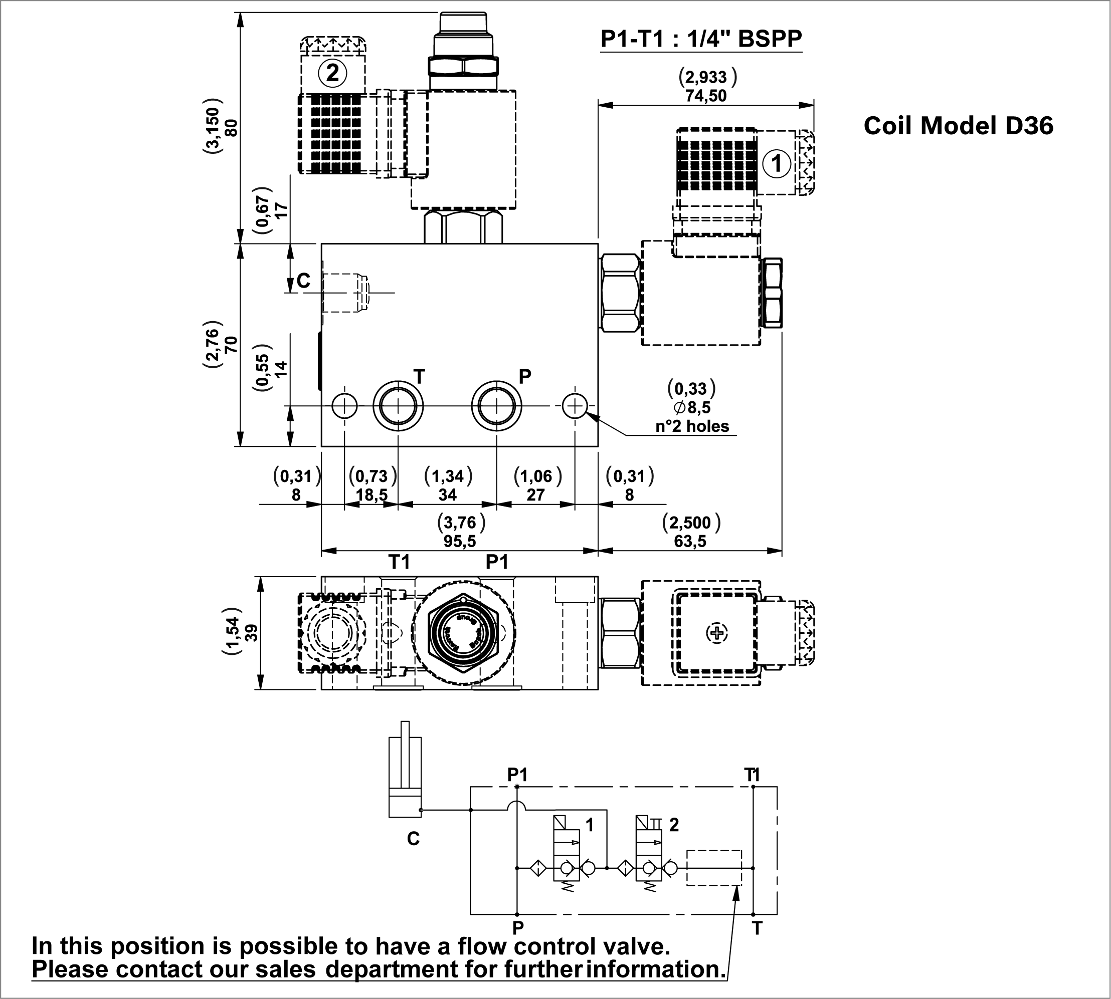
RE18306-01-154

Modular blocks to operate a single acting cylinder in a parallel circuit or a double acting cylinder in regenerative.

Each block includes 2 OR 2056 gaskets.

Minimum voltage required: 90% of nominal.

Coils not included, must be ordered separately.

For the selection of coil model and voltage please refer to page 41.

For the selection of connectors please refer to page 43.


Code
Description
Max working pressure bar (psi)
Max flow l/min (gpm)
Type
Material number
V07-14
Modular block with 2 VE with "C" port 1/4" BSPP
250 (3626)
25 (6,60)
G386507010A
R930062154
V07-38
Modular block with 2 VE with "C" port 3/8" BSPP
250 (3626)
25 (6,60)
G386507020A
R930064959

Modular blocks with four way three position solenoid valve. Spool type
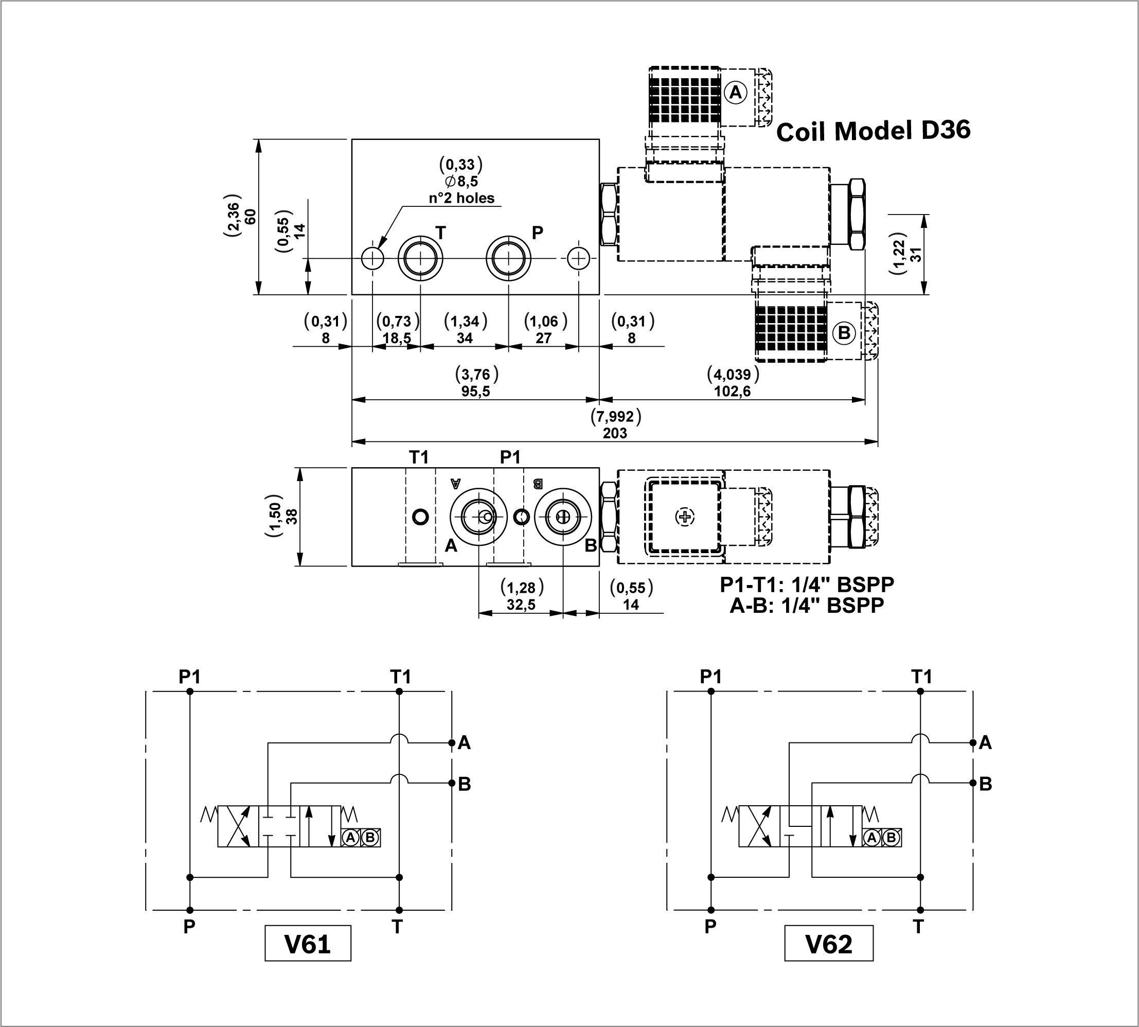
RE18306-01-155

A selection of modular blocks with 4/3 spool type solenoid valve for small double acting cylinders.

Each block includes 2 OR 2056 gaskets.

Minimum voltage required: 90% of nominal.

Coils not included, must be ordered separately.

For the selection of coil model and voltage please refer to page 41.

For the selection of connectors please refer to page 43.


Code
Description
Max working pressure bar (psi)
Max flow l/min (gpm)
Type
Material number
V61
Modular block with 4 way 3 position electric valve (V4.3A)
210 (3046)
10 (2,64)
G386562010A
R930063648
V62
Modular block with 4 way 3 position electric valve (V4.3B)
210 (3046)
10 (2,64)
G386563010A
R930067006

Modular block with four way three position solenoid valve and P.O. check valves on “A” and “B” line
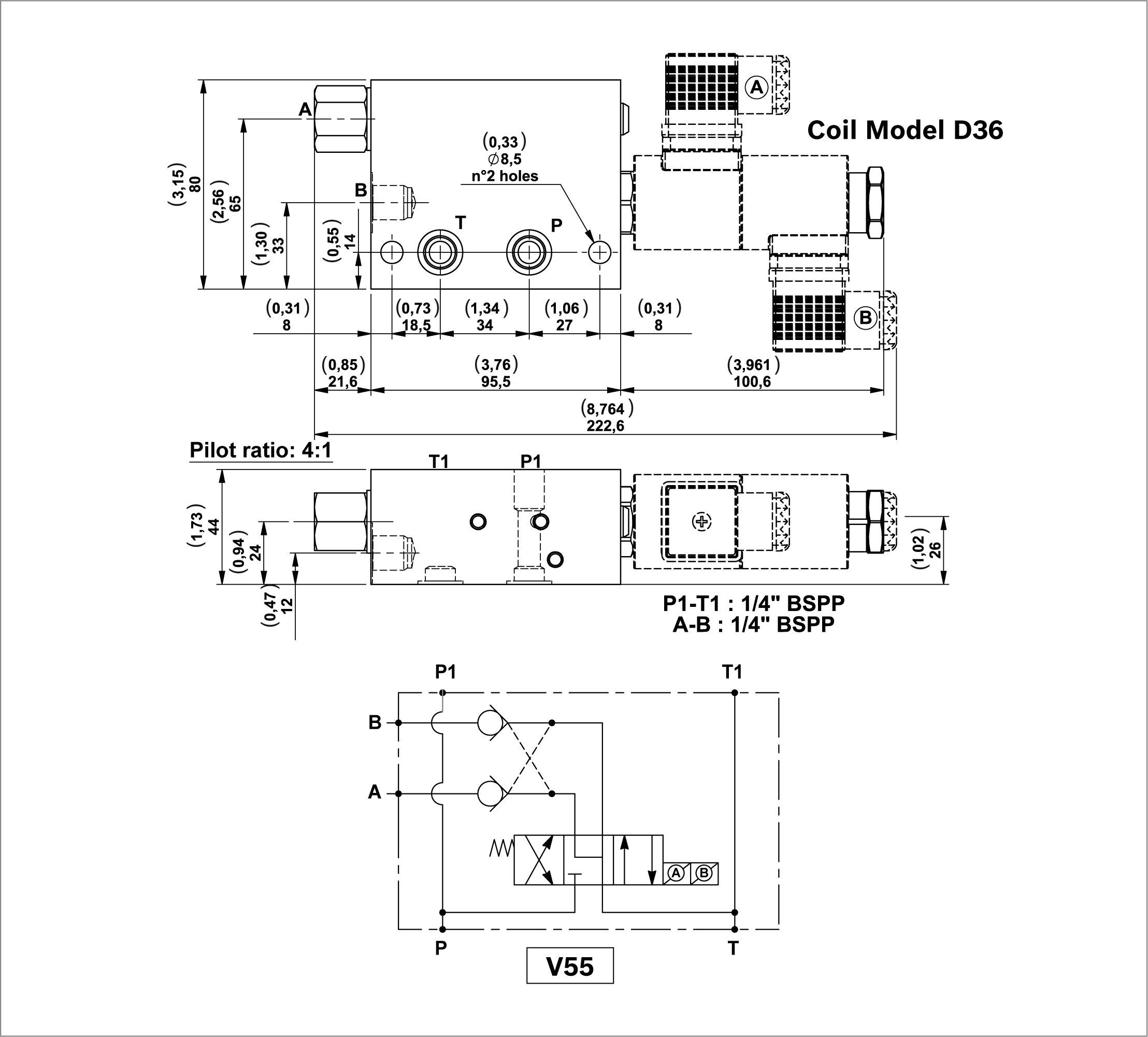
RE18306-01-156

A modular block with 4/3 spool type solenoid valve and P.O. check valves on “A” and “B” line. For small double acting cylinders.

Each block includes 2 OR 2056 gaskets.

Minimum voltage required: 90% of nominal.

Coils not included, must be ordered separately.

For the selection of coil model and voltage please refer to page 41.

For the selection of connectors please refer to page 43.


Code
Description
Max working pressure bar (psi)
Max flow l/min (gpm)
Type
Material number
V55
Modular block with 4 way 3 position electric valve and P.O. check valves on A and B without O-Ring on pilot piston
210 (3046)
10 (2,64)
G386591A10A
R930066516

Modular blocks with double locking solenoid valve
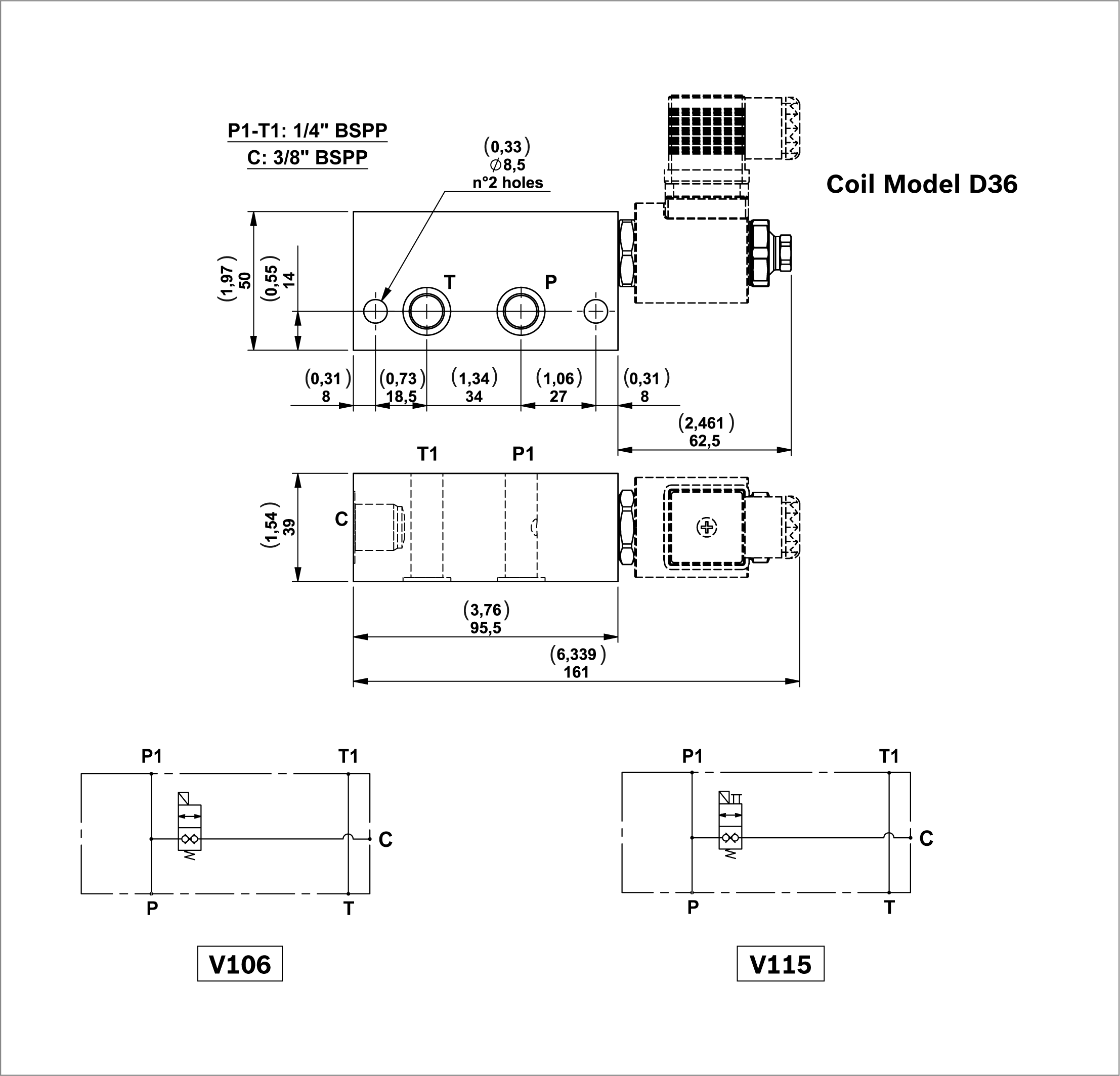
RE18306-01-157

Each block includes 2 OR 2056 gaskets.

Coils not included, must be ordered separately.

For the selection of coil model and voltage please refer to page 41.

For the selection of connectors please refer to page 43.


Code
Description
Max working pressure bar (psi)
Max flow l/min (gpm)
Type
Material number
V106
Modular block with DT solenoid valve
250 (3626)
15 (3,96)
G386606020A
R930064757
V115
Modular block with DTE solenoid valve
250 (3626)
15 (3,96)
1586500023A
R930061374

Isolator

RE18306-01-158
Code
Description
Type
Material Number
ES00
Straight isolator
EM14A
R930069418
ES90
90° isolator
EM14A-T
R930069419

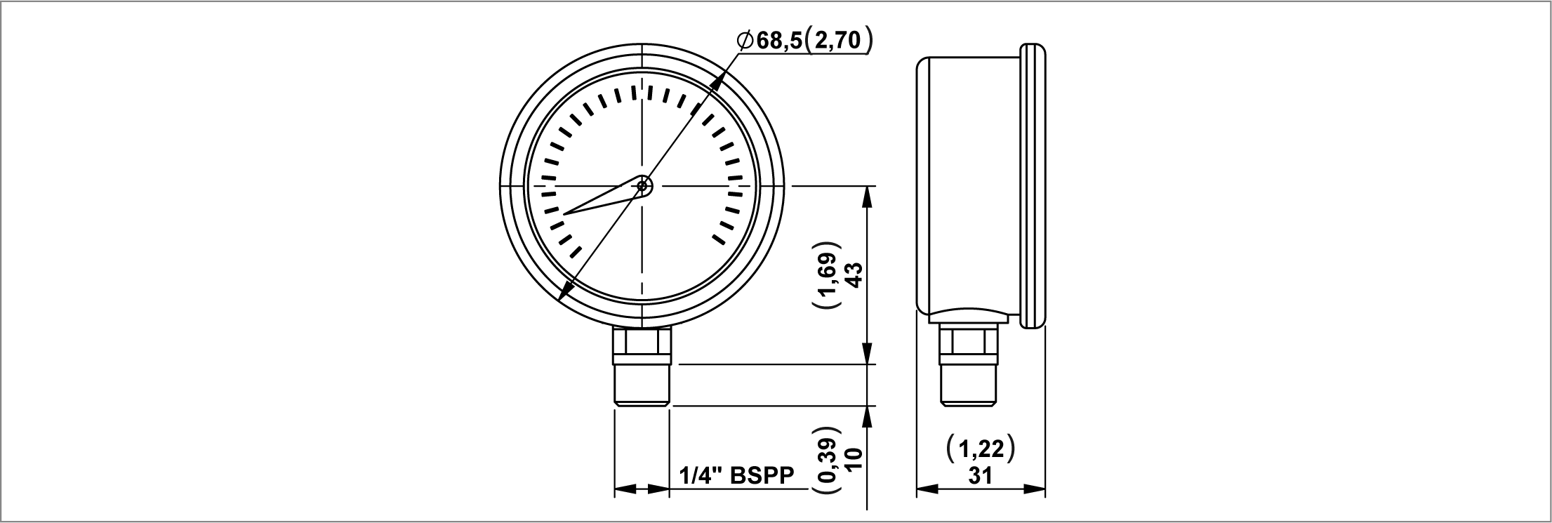
Manometer

RE18306-01-159
Code
Description
Pressure range bar (psi)
Type
Material Number
MN100
Pressure gauge
0-100 (0-1450)
C163017000
R932000582
MN160
Pressure gauge
0-160 (0-2320)
C163018000
R932000583
MN250
Pressure gauge
0-250 (0-3626)
C163019000
R932000584
MN315
Pressure gauge
0-315 (0-4568)
C163020000
R932000585

Pressure Switches

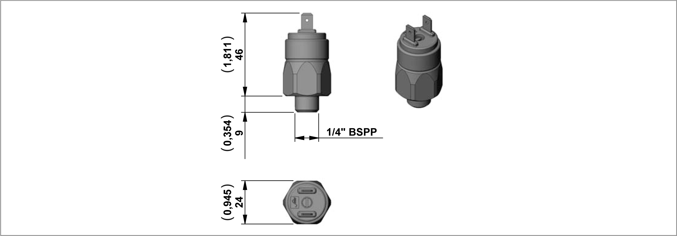
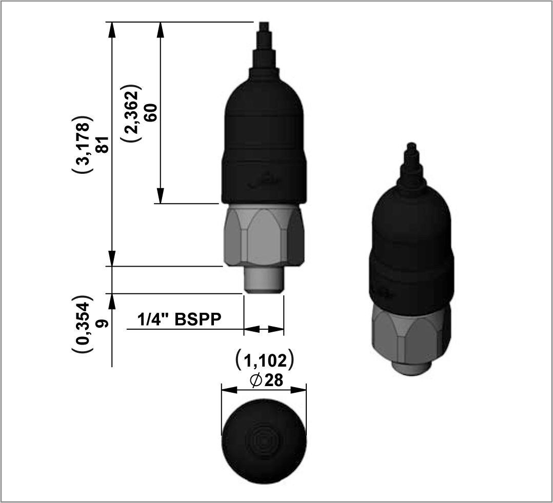
RE18306-01-160
Code
Adjustment Range bar (psi)
Contact Type
Internal Features
Protection(with protective cap assembled)
Type
Material Number
PRNO20
10-20 (145-290)
N.O.
Diaphragm
IP65
C164761000
R932010002
PRNC20
10-20 (145-290)
N.C.
Diaphragm
IP65
C164766000
R932010001
PRNO50
20-50 (290-725)
N.O.
Diaphragm
IP65
C164767000
R932010003
PRNC50
20-50 (290-725)
N.C.
Diaphragm
IP65
C164768000
R932010004
PRNO150
50-150 (725-2175)
N.O.
Piston
IP65
C164769000
R932010005
PRNC150
50-150 (725-2175)
N.C.
Piston
IP65
C164770000
R932010006

Protective Cap for Pressure Switches

RE18306-01-161
Code
Type
Material Number
CAP
F224013000
R932010000

Tank Diameter

Ø 96
Ø 123
Ø 190
Central Manifold
Oil tank diameter mm (inch)
Type
Material Number
ME
90 (3,54)
K2340S2177
R932011066
 
123 (4,84)
K2340S2175
R932011064
 
190 (7,48)
M234048000
R932003086

Vertical Suction, Plastic Pipe

RE18306-01-165
Central Manifold
Oil tank diameter mm (inch)
Type
Material Number
ME
33 (1,30)
K2340S2178
R932011067
 
43 (1,70)
K2340S2179
R932011068
 
49 (1,93)
K2340S2180
R932011069
 
54 (2,13)
K2340S2181
R932011070
 
61 (2,40)
K2340S2182
R932011071
 
77 (3,03)
K2340S2183
R932011072
 
87 (3,42)
K2340S2184
R932011073
 
99 (3,90)
K2340S2185
R932011074
 
114 (4,49)
K2340S2186
R932011075
 
136 (5,35)
K2340S2187
R932011076
 
161 (6,34)
K2340S2188
R932011077
 
241 (9,49)
K2340S2189
R932011078
 
321 (12,64)
K2340S2190
R932011079
 
381 (15,00)
K2340S2191
R932011080

Vertical Suction, Steel Pipe

RE18306-01-166
Central Manifold
H mm (inch)
Type
Material Number
ME
42 (1,65)
M234049000
R932003087
 
52 (2,05)
K2340S2009
R932002254
 
58 (2,28)
K234057000
R932002339
 
63 (2,48)
M2340S2163
R932009736
 
70 (2,76)
M234051000
R932003089
 
86 (3,39)
M234052000
R932003090
 
96 (3,78)
M234046000
R932003084
 
108 (4,25)
M234050000
R932003088
 
123 (4,84)
M234055000
R932003093
 
145 (5,71)
M234054000
R932003092
 
170 (6,69)
M234053000
R932003091
 
250 (9,84)
M234095000
R932003095
 
330 (12,99)
M234022000
R932003082

Suction Filter

RE18306-01-167
Compatibility
Filtering Degree (μm)
Max Flow l/min (gpm)
Type
Material Number
ME
90
8 (2,11)
K225583000
R932010867

Horizontal Return, Steel Pipe

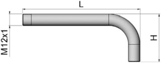
RE18306-01-168
L mm (inch)
H mm (inch)
Type
Material Number
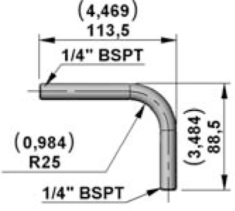
120 (4,72)
45 (1,77)
K234716000
R932002375
134 (5,28)
90 (3,54)
K234717000
R932002376
170 (6,69)
90 (3,54)
K234727000
R932002383

Vertical Return, Plastic Pipe

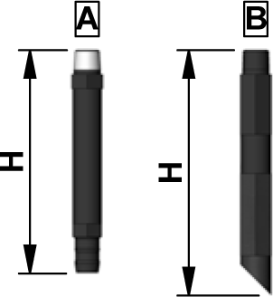
RE18306-01-169
H mm (inch)
Type
Material Number
Drawing ref.
100 (3,94)
K234715000
R932002374
A
110 (4,33)
K234780000
R932011081
B
120 (4,72)
K234781000
R932011082
B
150 (5,91)
K234714000
R932002373
A
160 (6,30)
K234782000
R932011083
B
200 (7,87)
K234713000
R932002372
A
250 (9,84)
K234784000
R932011084
B
300 (11,81)
K234785000
R932011085
B
400 (15,75)
K234786000
R932011086
B

Vertical Return, Steel Pipe

RE18306-01-170
H mm (inch)
Type
Material Number
250 (9,84)
K234718000
R932002377
300 (11,81)
K234719000
R932002378
400 (15,75)
K234722000
R932002379