

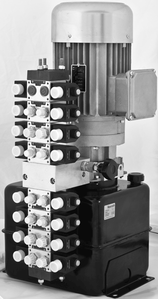
Compact Power Modules - K KE KS Series
K-KE-KS
Compact power modules KE, K, and KS series
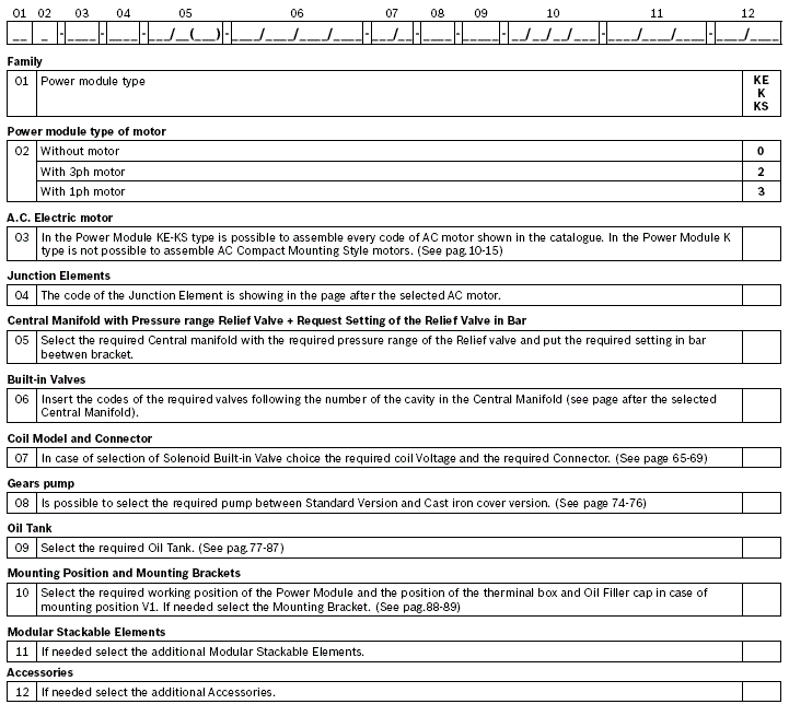
Ordering Details for Compact Power Modules with A.C. Motor
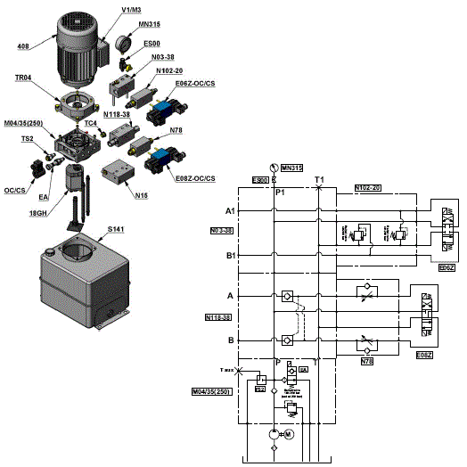
Example of Ordering Details for Compact Power Modules ME with A.C. Motor

Ordering Details for Compact Power Modules with AC Motor
Ordering Details for Compact Power Modules ME with D.C. Motor
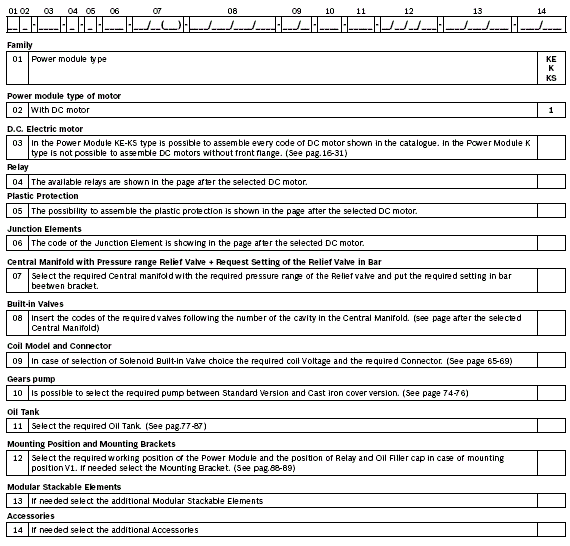
Example of Ordering Details for Compact Power Modules ME with D.C. Motor
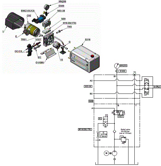
Ordering Details for Compact Power Modules with AC Motor
General Technical Data for Compact Power Module KE-K and KS series
Through the years DCOC has developed a highly evolved modular system resulting in powerful, flexible and cost effective power pack range, identified as “compact power modules”. In its easier configuration, a “compact power module” is an assembly of electric motor, central manifold with valves, pump, oil tank and a few connection elements. The central manifold, with its built-in valves, allows to achieve a large variety of hydraulic control circuits. If more complex circuits are needed, modular integrated blocks can be added by flange mounting, or interfacing, to the central manifold to extend its capabilities.
Typical applications
- Passenger lift
- Fork lift
- Car and motorcycle lift
- Lift table
- Dumper
- Tail gate
- Scissor lift
- Gangway and davits for boats
- Material handling
- Foods machinery
Power module selection
Choose the circuit which meets your application requirements.
Take note of all dimensions resulting from the basic components chosen for your application.
Note
dimensions may vary slightly and should be confirmed by DCOC, if the assembly is to be installed in a space with narrow clearance.
The tank capacity and the tank dimensions need to be large enough to assure proper pump suction: there must always be a reserve of oil in the tank when all cylinders are fully extended and avoid overflow when cylinders are fully retracted.
The tank must be evaluated also for best separation of air from oil, and for settling down oil contamination. It should be placed in a space with, at least, natural ventilation and it should permit enough heat dissipation to prevent high fluid temperature.
Select the electric motor by evaluating the power needed and the motor compliance with the heat developed during the expected run time (or “duty cycle”).
Hydraulic fluid for compact power module
Mineral oil based hydraulic fluids suitable for hydraulic systems can be used; they should have physical lubricating and chemical properties as specified by:
MINERAL OIL BASED HYDRAULIC FLUIDS HL
(DIN 51524 part 1)
MINERAL OIL BASED HYDRAULIC FLUIDS HL P
(DIN 51524 part 2)
For use of environmentally friendly fluids please consult DCOC.
Fluid viscosity, temperature range of the operating fluid, ambient temperature
The fluid viscosity should remain within the range 10 to 300 cSt (centistokes); recommended 15 to 120 cSt.
Permissive cold start viscosity is maximum 2000 cSt.
The fluid temperature should remain within the range -15°C and 80°C (5°F and 176°F).
NOTE
For compact power module with plastic tank the fluid temperature should remain within the range -15°C and 70°C (5°F and 158°F). Ambient temperature -15°C +40°C (5°F and 104°F).
Fluid cleanliness requirements and maintenance
We recommend a cleanliness of the operating fluid according to ISO 4406 Class 20/18/15 or cleaner. All components of the hydraulic circuit , including hoses and actuators, must be flushed and cleaned before assembling, because the compact power module has a suction filter only.
The hydraulic fluid should be replaced after the first 50 hours, and then every 1000 hours, or, at least, once a year.
Power module installation
The mounting position (is basically un-restricted; just avoid installations that could compromise the pump suction, it is recommended to support the power module on vibration dampening blocks when the mounting structure is expected to vibrate.
Wiring and starting-up
The wiring between battery and electric motor should be selected in order to avoid excessive voltage drop (recommended less than 1 V).
It is strictly forbidden to allow the backwards rotation of the pump even at the first starting: to prevent reverse rotation, the wiring polarities must be correctly connected (except for the reversible pumps).
NOTE
Caution: when energized, the surface temperature of the electric motor could reach temperature levels of 60-80°C (140-176°F): care should be taken to avoid any accidental contact of people with the motor surface.
A.C. motors
The tolerances on the nominal voltage are:
Single phase motor: 230V +/-5% -
Three phase motor: 230-400V +/-10%.
Protection degree : IP54 (protection against dust and water splash).
Insulation class: F (155°C) (311°F).
All motors are aluminum alloy die cast without painting.
NOTE
Standard Single phase motors have a permanently connected run capacitor. If the motor starts with pressure in the circuit (load in the actuator) we suggest the use of specials dedicated manifolds KE series with integrated Start-Up valve (Manifold code M09 and M19).
D.C. Motors
DCOC has a wide range of D.C. motors. In the following pages you will find a selection of our standard range. For further information about our complete range please contact our Sales department.
All the motors shown have clockwise rotation suitable for driving our counter clockwise gear pumps.
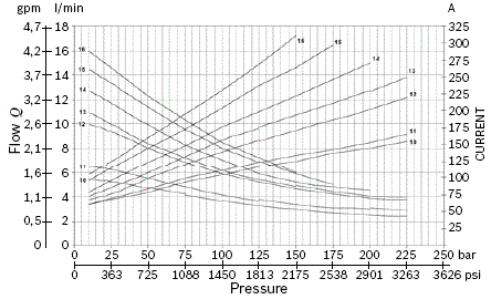
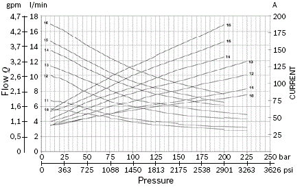
For each motor a diagram is shown that enables the customer to select the right pump displacement needed for the required flow and working pressure.
To be sure of selecting the best electric motor for the application, also the duty cycle has to be verified.
Following are the definitions of the type of duty cycles:
S2 = Short time duty cycle: indicate the number of minutes the motor can operate before reaching the maximum allowable temperature. After this time the motor must cool down until the ambient temperature is reached.
S3 = Intermittent duty cycle: indicate the maximum time percentage (%) based on 10 minute period within the motor can run until reaching the maximum allowable temperature. For example an S3 value of 15% = 1,5 minutes running time every 10 minutes period. For 8,5 minutes the motor is switched-off.
The S2 and S3 values are related to the current draw. On the label of motor are indicated the S2 and S3 values referred to the nominal power of the motor.
To check the S2 or S3 value at different conditions is necessary to find the value of current in the motor-pumps diagram and related it with the represented list.
All the diagrams motor-pumps are obtained at the nominal voltage of 12 or 24 Volt using fluid ISO VG 46 at 20-30°C (68-86°F).
Central manifolds
All the Central Manifolds shown in the catalogue are made in die cast aluminium alloy except the manifold code 10 for CPM MR series that is made by extruded bar. The validation of the Central Manifolds follows a life-test with 250 bar (625 psi) pulsed pressure repeated for 300.000 cycles.
Built-in valves
A wide range of cartridge valves and special plugs is available to be assembled in our Central Manifolds. The cartridge valves shown are designed for use in our Compact Power Module and are manufactured using steel with high mechanical strength. Surface treatments protect the exposed parts to the external environment. Standard seals are NBR (BUNA-N) with backup rings in PTFE. The cartridge valves with “leak proof seat design” have an average leakage of 10-15 drops/minute (< 1 cm3/minute 0.06 in3/min.) at the maximum pressure using fluid ISO VG46 at 40°C (104°F). The validation of the cartridge valves follows a life-test at pulsed maximum pressure (indicated for each valve) repeated for 500.000 cycles.
All the solenoid cartridge valves are fitted with protective O-Rings installed between the pole tube and the coil. These O-Rings protect the internal parts from condensation and contaminants , which could cause malfunction.
All the solenoid cartridge valves are designed for operating in D.C.
Power supply in A.C. requires a connector with bridge rectifier included.
External gear pumps
DCOC offers a wide range of External Gear Pumps to cover different kinds of applications. The standard versions are suitable for the biggest part of applications. For applications requiring higher peaks of pressure (for example Car Lift and Presses) a version with cast iron covers is available. For applications requiring high numbers of Start&Stop or low noise feature the tapered shaft version for elastic coupling is preferred (available only for central manifold K series with A.C. motors). All the pumps are pressure compensated to guarantee the best efficiency.
Oil tanks
In this catalogue you will find a wide selection of steel and plastic tanks available as a standard product. If a special tank is required please contact our Sales Department. Steel tanks have Black paint finish and are suitable for operating temperature range -15°C / +80°C (5°F / 176°F). Plastic tanks are obtained in one piece in order to avoid welded parts that are weak points at extreme temperature and vibrations. Plastic tanks are suitable for operating temperature range -15°C / +70°C (5°F / 158°F).
NOTE
even if the plastic tank mounting system is designed to avoid oil leakage the tank must be securely anchored when fitted in mobile equipment and when subject to shocks and heavy vibrations. Please check that the anchorages do not stress or deform the tank.
Modular stackable elements
Our modular system offers a wide range of standardised elements. They are divided in two main series:
Modular Elements “N” series: Modular blocks for different mounting position with mechanical valve or interface for CETOP valves to create parallel or series circuits. Modular Elements “V” series: Modular blocks that incorporate solenoid operated cartridge valves 2,3,4 way. All the Modular Elements are made in extruded aluminum alloy. In the catalogue you will find a selection of the main used models.
NOTE
To reduce the complexity of the system and optimize the available space, special Modular Elements can be designed and manufactured following the customers needs. In this case please contact our Sales Department.
European machine directive 2006/42/CE
According to the Machine Directive 2006/42/CE, a complete power module, as described in paragraph 15 and made available to the European market, enters into the definition of “partly completed machinery”.
Instead, the power module sub-assemblies (motor, pump, reservoir, central manifold,...), when not assembled into a complete power pack, are considered “components” which can be employed in a “machinery” or a “partly completed machinery”. In this case, the DCOC components and sub-assemblies must be fitted in compliance with all the relevant technical data sheet applicable to the product, and shall not be operated, adjusted or disassembled before the complete machinery where they are incorporated has been declared to be in compliance with the Machine Directive 2006/42/CE.
NOTE
All the components shown in the catalogue ARE NOT suitable for use in potentially explosive atmosphere.
Technical information
Below you will find the most common equations used in hydraulics:
Compact Power Module Type
Standard Type KE series
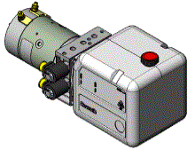
Complex circuits, direct flange AC motors.
DC motors up to 3000 W.
AC motors up to 4000 W (5, 5 hp).
Pump displacement up to 7,9 cm3 (0,31 inch3).
Pressure up to 300 bar (4350 psi).
Optionals:
Start-up valve inside.
3-ways solenoid operated valve inside.
4-ways solenoid operated valve inside.
AC electric motor with direct coupling for smaller dimensions.
Gear pumps with splined shaft.
Low noise pumps.
Optional Type K series
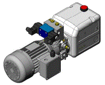
Standardized central manifold for simple hydraulics circuits.
DC motors up to 3000 W.
AC motors up to 4000 W (5,5 hp).
Pump displacement up to 7,9 cm3 (0,31 inch3).
Pressure up to 300 bar (4350 psi).
Optionals:
Elastic coupling.
Optional Type KS series
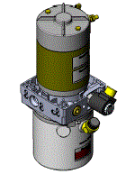
Designed for lifting applications.
Ready solution for simple acting circuits with the possibility of unloading valve.
DC motors up to 3000 W.
AC motors up to 4000 W (5,5 hp).
Pump displacement up to 7,9 cm3 (0,31 inch3).
Pressure up to 300 bar (4350 psi).
NOTE
that every power module type can be mounted in horizontal or vertical position.
A.C. Electric Motors Standard Flange
Standard A.C. Motors in B14 form.
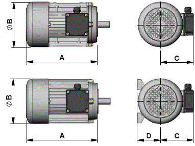
4 Poles Three Phase
Current Motors 230/400V 50Hz IP54 (1450 rpm at 50Hz)
Standard A.C. Motors in B14 form.
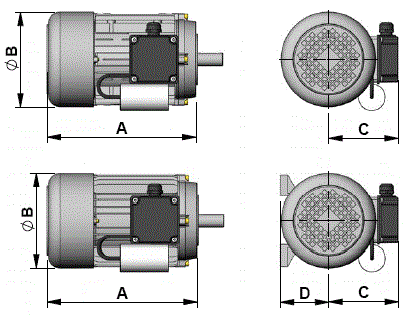
On request motors in B34 form are avaible. In this cases, please put “B34” after the code of the motor when filling in the description. Example “408MB34”.
4 Poles Single Phase
Current Motors 230V 50Hz Form B14 Protection IP54 (1450 rpm at 50Hz)
NOTE
The electric motors with standard flange shown in this pages are delivered by different certified suppliers. This means the indicated dimensions could change a little, depending on which manufacturer will be assembled. On the CPM the choice of the manufacturer is based on our stock availability.
Junction Elements for A.C. Electric Motor Standard Flange
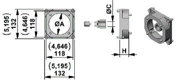
Junction Elements for manifolds KE and KS series (STD COUPLINGS)
Junction Elements for manifolds KE and KS series (COUPLINGS FOR SPLINED SHAFT PUMPS)
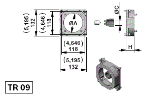
Junction Elements for manifolds K series (STD COUPLINGS)

Junction Elements for manifolds K series (ELASTIC COUPLINGS)
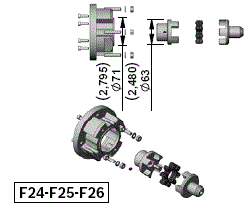
NOTE
The flanges shown in this page have the same dimensions as per the flanges used for standard couplings. The elastic couplings are suggested for applications requiring low noise and applications with high frequency of START/STOP operations.
A.C. Electric Motor Compact Mounting Style for Power Module Type KE and KS
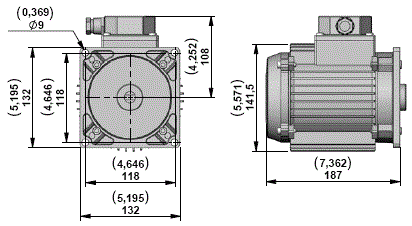
These motors are designed to reduce the overall dimensions and the cost of the junction elements.
They can be assembled only in the manifold KE and KS series.
Three Phase Current Motors 230/400V 50Hz IP54 Size IEC 71
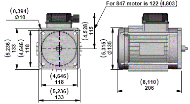
Three Phase Current Motors 230/400V 50Hz IP54 Size IEC 80
NOTE
The motors shown in these tables are a selection of our range. In case of needs of different technical characteristics PLEASE CONTACT OUR SALES DEPARTEMENT. The electric motors with compact mounting style shown in this pages are delivered by different certified suppliers. This means the indicated dimensions could change a little, depending on which manufacturer will be assembled. On the CPM the choice of the manufacturer is based on our stock availability.
Junction Elements for A.C. Electric Motor Compact Mounting Style for Power Module Type KE and KS

Junction Elements for manifolds KE and KS series
Junction Elements for A.C. Electric Motor Compact Mounting Style for Power Module Type KE and KS with splined shaft pumps
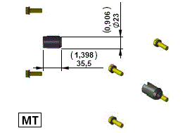
Junction Elements for manifolds KE and KS series
D.C. Electric Motors Standard Performance
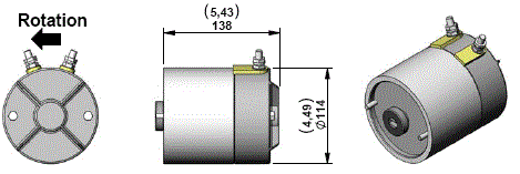
Electric Motor C200 (24V – 1300W) Diagrams
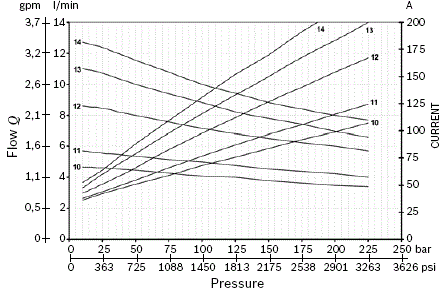
S2 - S3 performance
NOTE
The values of the curves may change slightly depending on the brand / model of pump that is mounted.
Relay
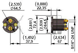
Starting Relay Standard Performance
Kit Motor + Relay
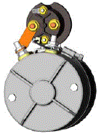
Junction Elements for D.C. Electric STD motor flange
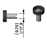
Junction Elements for manifolds KE and KS series
NOTE
Suitable for KE and KS only.
D.C. Electric Motors Standard Performance
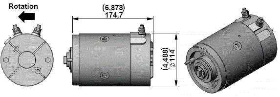
Electric Motor C190-191 (12V – 1600W) Diagrams
S2 - S3 performance
Electric Motor C192 - C193 (24V – 2200W) Diagrams
S2 - S3 performance
NOTE
The values of the curves may change slightly depending on the brand / model of pump that is mounted.
Relay

Starting Relay Standard Performance (Pict. 1)
Starting Relay High Performance (silver plate contact) (Pict. 2)
Kit Motor + Relay
Plastic Protection
Kit for assembly plastic protection
Junction Elements for D.C. Electric Motor
Junction Elements for manifolds
D.C. Electric Motors High Performance
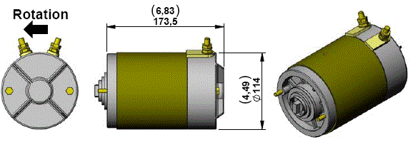
Electric Motor C91-C102 (12V – 1600W) Diagrams
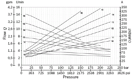
S2 - S3 performance
Electric Motor C92-C103 (24V – 2200W) Diagrams
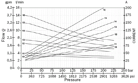
S2 - S3 performance
NOTE
The values of the curves may change slightly depending on the brand / model of pump that is mounted.
Relay

Starting Relay Standard Performance (Pict. 1)
Starting Relay High Performance (silver plate contact) (Pict. 2)
Kit Motor + Relay
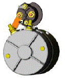
Plastic Protection
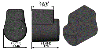
Junction Elements for D.C. Electric Motor
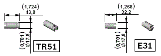
Junction Elements for manifolds
D.C. Electric Motors Standard Performance Low Noise

Electric Motor C194 (24V – 2200W) Diagrams
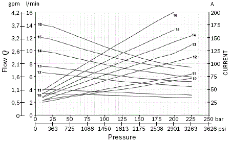
S2 - S3 performance
NOTE
The values of the curves may change slightly depending on the brand / model of pump that is mounted.
Relay
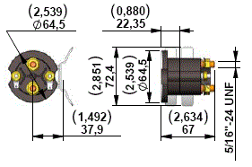
Starting Relay Standard Performance (Pict. 1)
Kit Motor + Relay
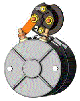
Junction Elements for D.C. Electric STD motor flange
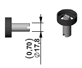
Junction Elements for manifolds KE and KS series
NOTE
Suitable for KE and KS only.
D.C. Electric Motors High Performance Fan Cooled
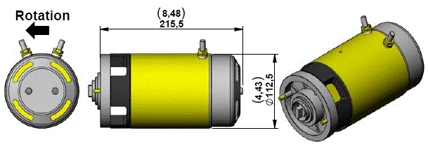
Electric Motor C78 (12V – 1500W) Diagrams
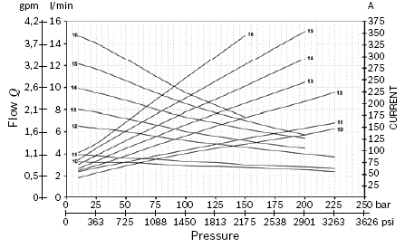
S2 - S3 performance
Electric Motor C79 (24V – 2000W) Diagrams
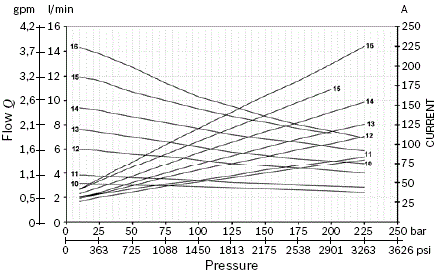
S2 - S3 performance
NOTE
The values of the curves may change slightly depending on the brand / model of pump that is mounted.
Relay

Starting Relay Standard Performance (Pict. 1)
Starting Relay High Performance (silver plate contact) (Pict. 2)
Kit Motor + Relay
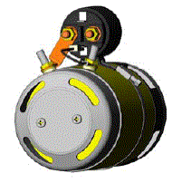
Junction Elements for D.C. Electric Motor
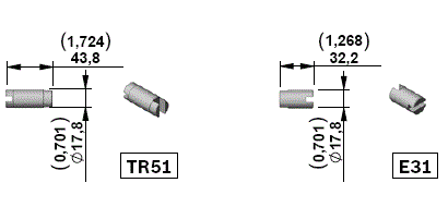
Junction Elements for manifolds
D.C. Electric Motors Standard Performance

Electric Motor C201 (24V – 3000W) Diagrams
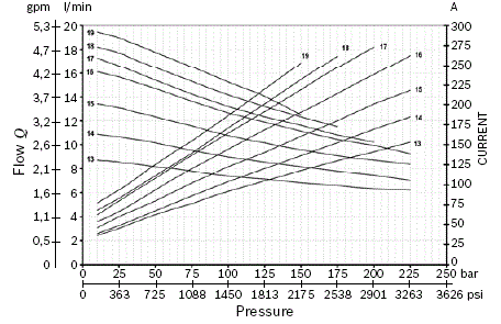
S2-S3 performance
NOTE
The values of the curves may change slightly depending on the brand / model of pump that is mounted.
Relay
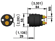
Starting Relay High Performance (silver plate contact)
Kit Motor + Relay
Junction Elements for D.C. Electric Motor Standard Flange
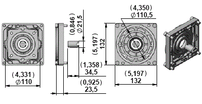
Junction Elements for manifolds KE and KS series
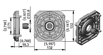
Junction Elements for manifolds K series
D.C. Electric Motors Low Noise High Performance
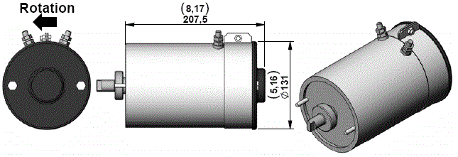
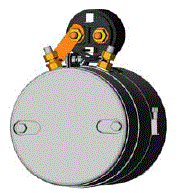
Electric Motor C151-C140 (24V – 3000W) Diagrams
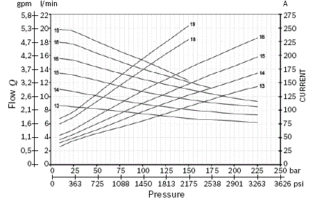
S2-S3 performance
NOTE
The values of the curves may change slightly depending on the brand / model of pump that is mounted.
Relay
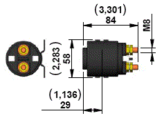
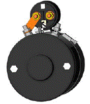
Starting Relay High Performance (silver plate contact)
Kit Motor + Relay
Junction Elements for D.C. Electric Motor Standard Flange
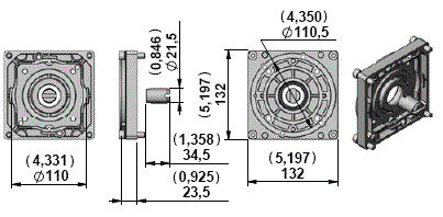
Junction Elements for manifolds KE and KS series
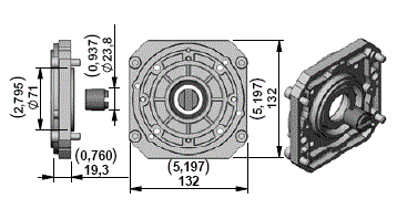
Junction Elements for manifolds K series
D.C. Electric Motors High Performance Fan Cooled

Electric Motor C111 (24V – 3000W) Diagrams
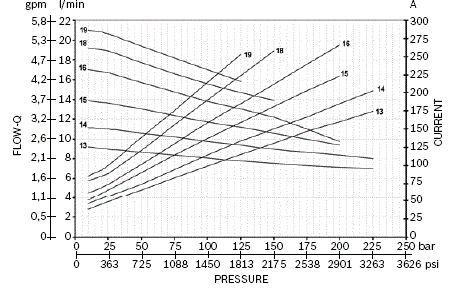
S2-S3 performance
NOTE
The values of the curves may change slightly depending on the brand / model of pump that is mounted.
Relay
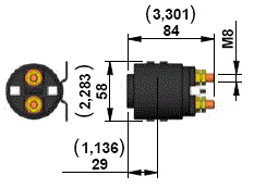
Starting Relay High Performance (silver plate contact)
Kit Motor + Relay
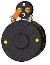
Junction Elements for D.C. Electric Motor Standard Flange
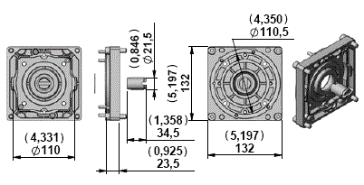
Junction Elements for manifolds KE and KS series

Central Manifold KE
M02
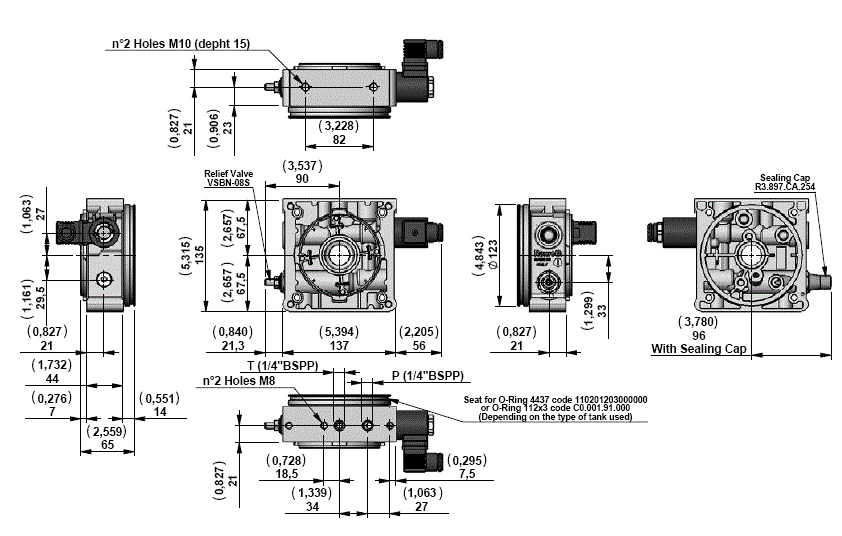
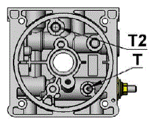
View Manifold Tank side
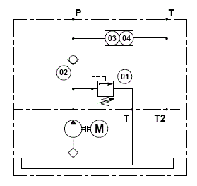
Manifold Hydraulic Diagram
M02 with valves
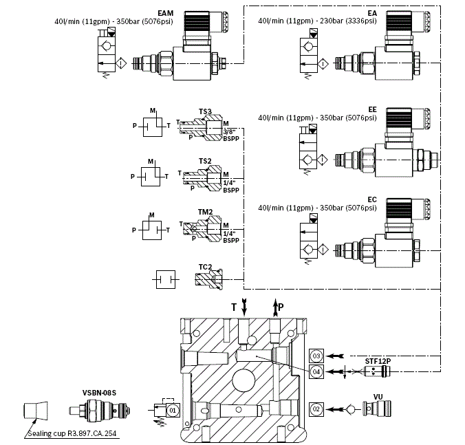
Main Realizable Diagrams
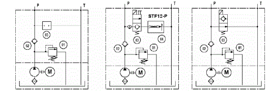
M03

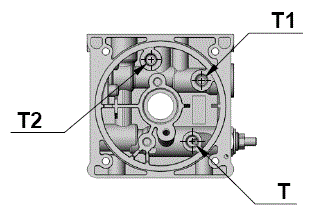
View Manifold Tank side
Manifold Hydraulic Diagram
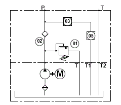
M03 with valves
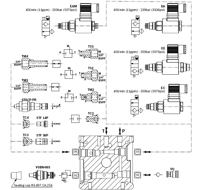
Main Realizable Diagrams
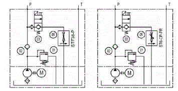
M09
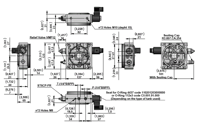
View Manifold Tank side
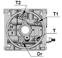
Manifold Hydraulic Diagram
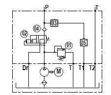
M09 with valves
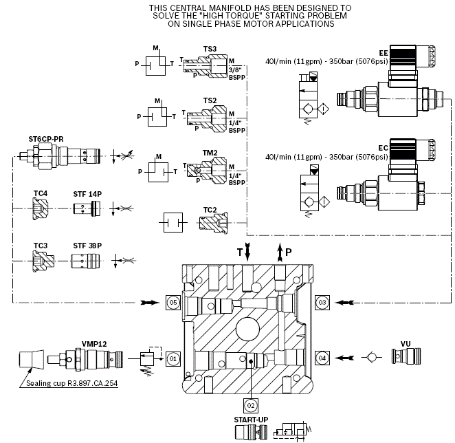
Main Realizable Diagrams

M04
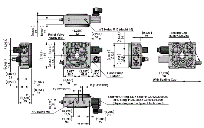
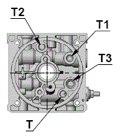
View Manifold Tank side
Manifold Hydraulic Diagram
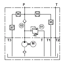
M04 with valves
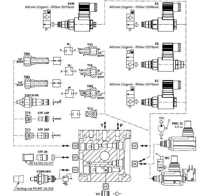
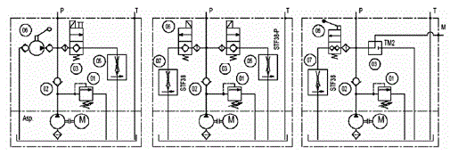
Main Realizable Diagrams
M05
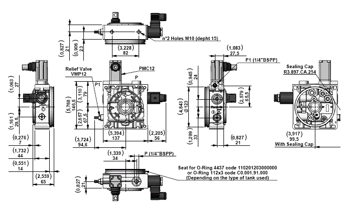
View Manifold Tank side
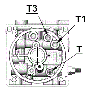
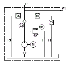
Manifold Hydraulic Diagram
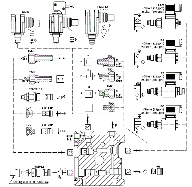
M05 with valves
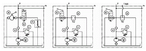
Main Realizable Diagrams
M15
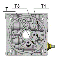
View Manifold Tank side
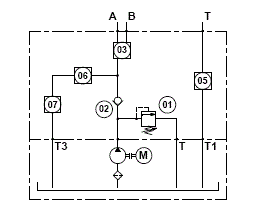
Manifold Hydraulic Diagram
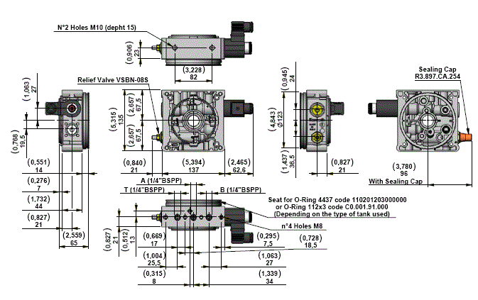
M15 with valves
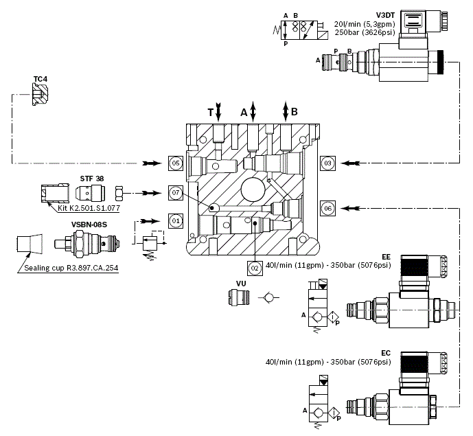
Main Realizable Diagrams
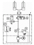
M16
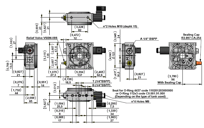
View Manifold Tank side
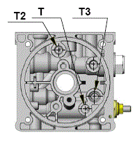
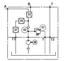
Manifold Hydraulic Diagram
M16 with valves
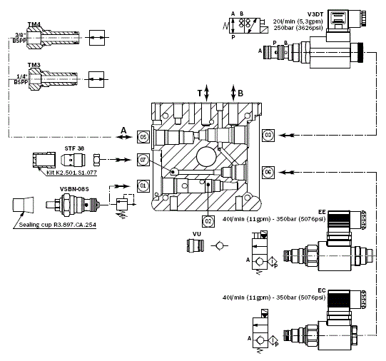
Main Realizable Diagrams
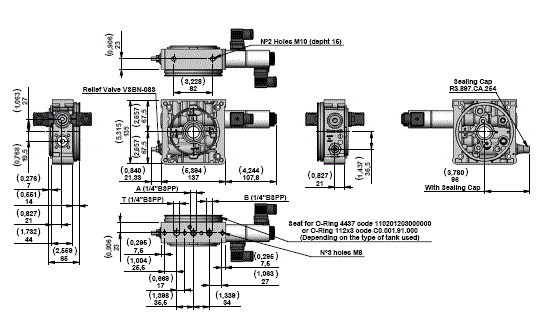
M25
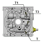
View Manifold Tank side
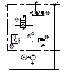
Manifold Hydraulic Diagram
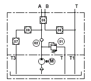
M25 with valves
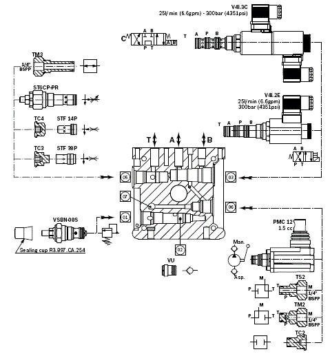
Main Realizable Diagrams

M32
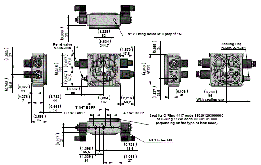
View Manifold Tank side
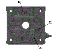
Manifold Hydraulic Diagram
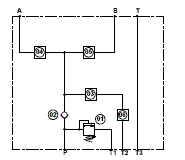
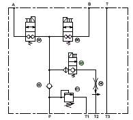
M32 with valves
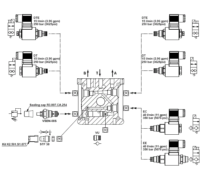
Main Realizable Diagrams
Central Manifold K
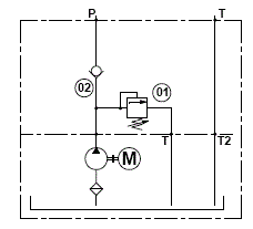
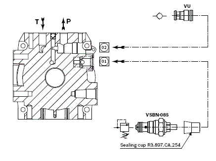
A1
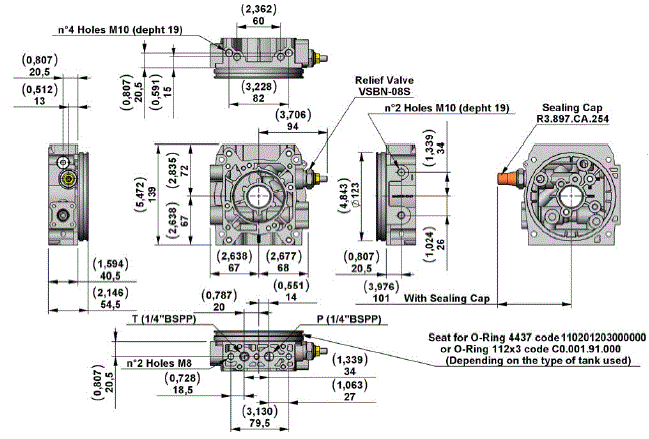
View Manifold Tank side
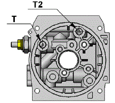
Manifold Hydraulic Diagram
A1 with valves
A12
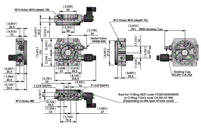
View Manifold Tank side
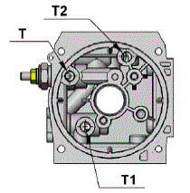
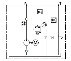
Manifold Hydraulic Diagram
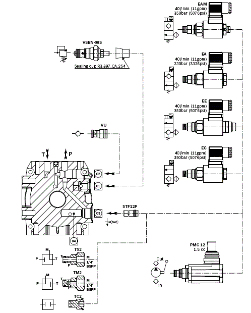
A12 with valves
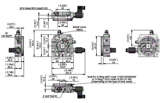
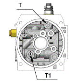
A9
View Manifold Tank side
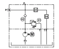
Manifold Hydraulic Diagram
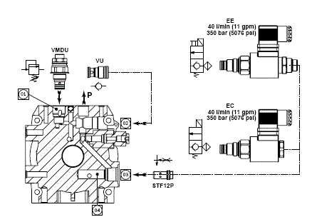
A9 with valves
Central Manifold KS
KS05
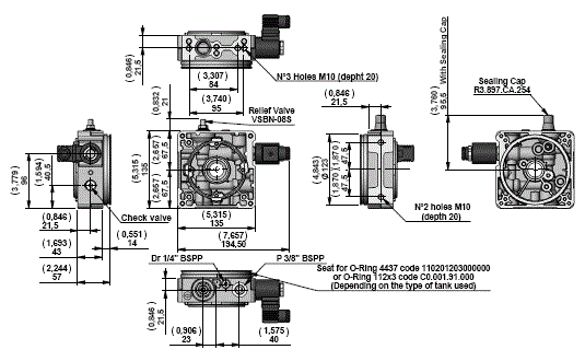
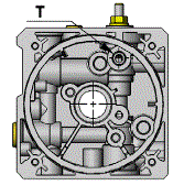
View Manifold Tank side
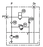
Manifold Hydraulic Diagram
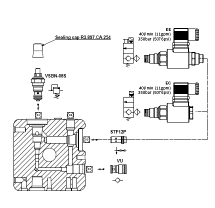
KS05 with valves
NOTE
Steel tank is not available for central manifold KS type. Please contact our sales department for further information.
KS02
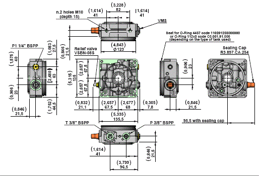
NOTE
Steel tank is not available for central manifold KS type. Please contact our sales department for further information.
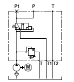
View Manifold Tank side
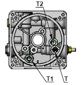
Manifold Hydraulic Diagram
Built-in Valve
EC-EE Series
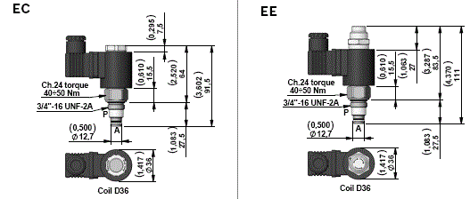
2 Way Pilot Operated Solenoid Valves, Normally Closed for D.C. current
Description
This is a standard 2 way pilot operated valves poppet style.
- Only for D.C. current.
- Internal leakage: see technical data.
- Minimum operating voltage: 90% of nominal.
- Screen on P 300 Micron.
- Screw Type Emergency on EE.
Valve symbol


Technical Data
D36 Coil Voltage Available
NOTE: For more info see Data Sheet RE18323-25
EA-EAM Series
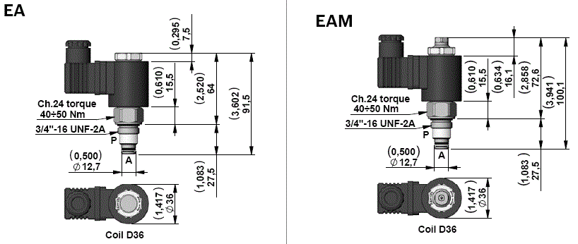
2 Way Pilot Operated Solenoid Valves, Normally Open
Description
This is a standard 2 way pilot operated valves poppet style.
- Only for D.C. current.
- Internal leakage: see technical data.
- Minimum operating voltage: 90% of nominal.
- Screen on P 300 Micron.
- Push Type Emergency on EAM.
Valve symbol


Technical Data
D36 Coil Voltage Available
NOTE: For more info see Data Sheet RE18323-25
DT-DTE Series (for manifold M32)
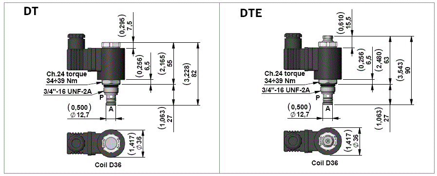
2 Way direct acting double lock Solenoid Valves, Normally Closed for D.C. current
Description
On this valve the oil can pass free or can be perfectly locked on each ports “P” and “A”.
- Only for D.C. current.
- Internal leakage: see technical data.
- Minimum operating voltage: 90% of nominal.
- Push Type Emergency on DTE push..
Valve symbol


Technical Data
D36 Coil Voltage Available
NOTE: For more info see Data Sheet RE18324-02 V3D-DT Series
V3D-DT Series
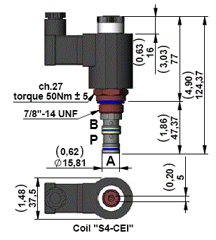
3 Way Direct Acting Poppet Style Solenoid Valves
Description
3 Way Direct Acting Poppet Style Solenoid Valves
- Only for D.C. current.
- Internal leakage: see technical data.
- Minimum operating voltage: 90% of nominal.
- Push Type Emergency.
Valve symbol

Technical Data
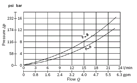
S4-CEI Coil Voltage Available
V4D-CEI-2P Series
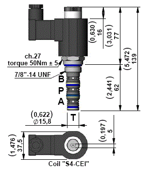
4 Way 2 Position Solenoid Valves Spool Type
Description
4 Way 2 Position Solenoid Valves, Spool Type
- Only for D.C. current.
- Minimum operating voltage: 90% of nominal.
- Push Type Emergency.
Valve symbol

Technical Data
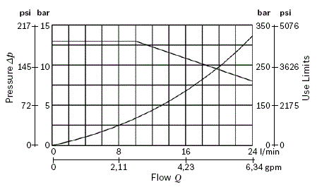
S4-CEI Coil Voltage Available
V4I.3C Series
4 Way 3 Position Solenoid Valves Spool Type
Description
4 Way 3 Position Solenoid Valves, Spool Type
- Only for D.C. current.
- Minimum operating voltage: 90% of nominal.
- Push Type Emergency (only function coil B).
Valve symbol

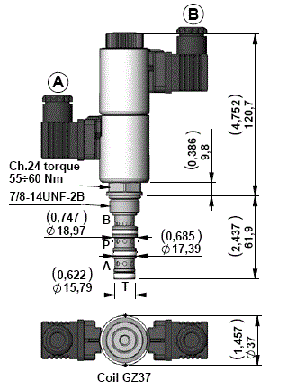
Technical Data
GZ37 Coil Voltage Available
NOTE
For more info see Data Sheet RE18324-64
Coils - Connectors
Technical Data
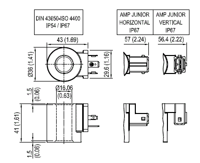
Weight: 0.18 kg (0.40 lbs)
Power: 20 W
Heat insulation Class H: 180°C (356°F)
Ambient temperature range: -30/+90°C (-22/+194°F)
Further performance limits in terms of temperature and voltage fluctuations: please refer to data sheet of the solenoid valve where D36 coil is mounted.
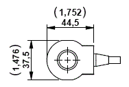
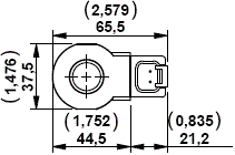
Coils D36 DIN 43650
NOTE
* OU and AH versions especially designed in cases of AC supply voltage (respectively for 110AC and 220 AC) to be used in conjunction with connector with circuit including wave rectifier. Ambient temperature range for OU and AH versions: -30°C / + 75°C
Coils D36 AMP H
Coils D36 AMP V
Coils D36 Deutsch L
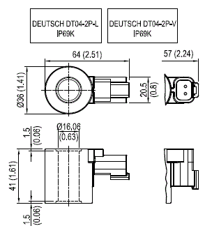
Coils D36 Deutsch V
Coils D36 Single Lead
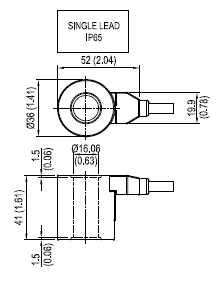
NOTE
For more info see Data Sheet RE18325-90
Technical Data
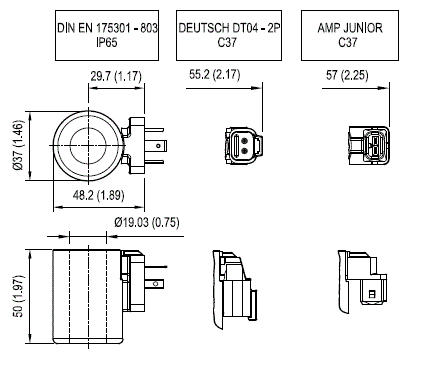
Weight: 0.24 kg (0.53 lbs)
Heat insulation Class H: 180°C (356°F)
Ambient temperature range: -40/+110°C (-40/+230°F)
Inlet voltage fluctuations must not exceed ±15% of nominal voltage to obtain correct operation and long life coils.
Coils are not equipped with suppression diode. Coating to DIN 50962 - Fe // ZnNi with thick film passivation.
(Salt spray test to DIN 50021 720 h)
Coils GZ37 DIN 43650
Coils GZ37 Deutsch V
Coils GZ37 AMP V
NOTE
For more info see Data Sheet RE18325-90
COIL Model S4-CEI – 26W – ED 100% for valves V3D-DT , V4D-CEI-2P , V4D-CEI-3P Series
Coil protection: Polyamide resin with fiber glass for Heat insulation class F (155°C) (311°F).
Solenoids “S4-CEI” (18 W) are designed for continuos duty ED100%.
Ambient temperature range: -15°/+40°
Inlet voltage fluctuations must not exceed +/- 10% of nominal voltage to obtain correct operations and long life coils Protection degree: see tables below
DIN 43650 - ISO 4400 IP65 with connector assembled
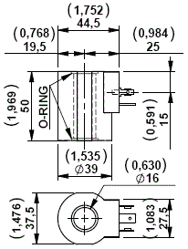
AMP JUNIOR IP67
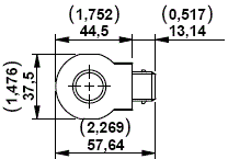
SINGLE LEAD IP54
DEUTSCH DT04-2P-V IP67
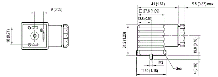
CONNECTOR IP67 - EN175000 (DIN 4350-A) / ISO 4400
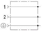
Standard Circuit
Circuit with VDR + Wave Rectifier
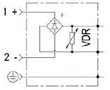
NOTES
Diode with capacity max 1 Amp.
Black is the standard colour. Grey is used in case of valves with 2 coils (V4DS-3P and V4D-CEI-3P Series).
MC
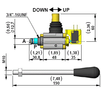
Technical Data
2 Way Manual Operated Cartridge Valve

MCR
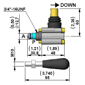
Technical Data
2 Way Manual Operated Cartridge Valve

PMC12
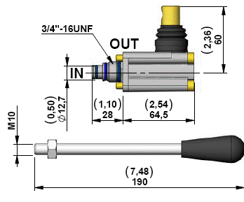
Technical Data
Hand pump (1.5cc)

Plug for Cavity
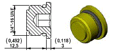
Plug for Cavity
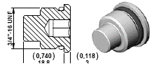
Plug for Cavity
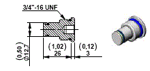

1/4” Auxiliary Return Port
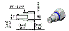

3/8” Auxiliary Return Port
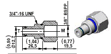

1/4” Auxiliary Pressure Port
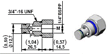

1/4” Auxiliary Pressure Port
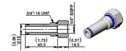

3/8” Auxiliary Pressure Port
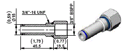

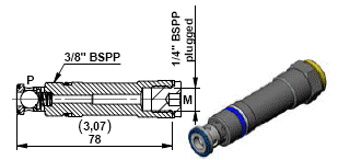
Check Valve with Pressure Port 1/4” BSPP for manifolds K series

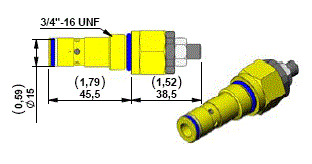
Pressure Compensated Flow Regulator

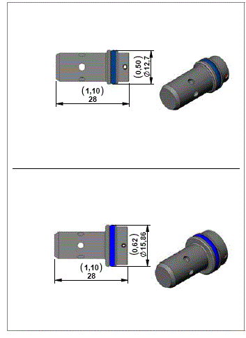
Technical Data
Flow Control Valves Pressure Compensated


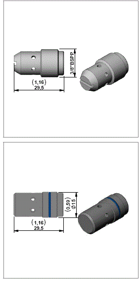
Flow Control Valves Pressure Compensated


Gear Pumps Group 1 for KE - K - KS
Standard Version

High Pressure Gear Pumps Group 1 for KE - K - KS Cast iron covers version for high pressure applications

NOTE
All pumps have anti-clockwise rotation.
Gear Pumps Group 1 for K
Elastic couplings version with tapered shaft*

NOTE
*Note
The assembly of the gear pumps with tapered shaft are only possible in the manifolds K series with the following junction elements:
- Motor size IEC71: junction element code F82
- Motor size IEC80: junction element code F24
- Motor size IEC90: junction element code F25
- Motor size IEC100-112: junction element code F26
Gear Pumps
Gear Pumps Group 1 with Splined Shaft for KE-KS central manifold
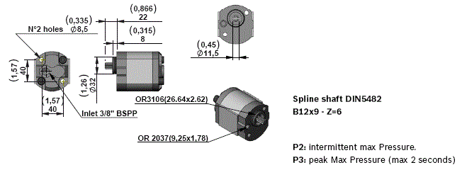
Silent Gear Pumps Group 1 for KE - K - KS

NOTE
All pumps have anti-clockwise rotation.
Oil Tanks for KE - K - KS
Technical Data for Plastic Tanks
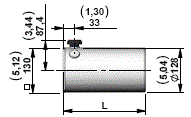
For this tanks is necessary to use the O-RING Ø112x3 code: C000191000 R-Number: R932000190
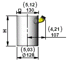
For this tanks is necessary to use the O-RING Ø112x3 code: C000191000 R-Number: R932000190
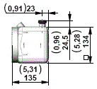
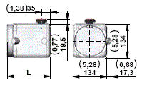
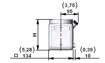
Plastic Tanks
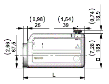
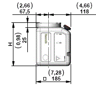
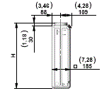
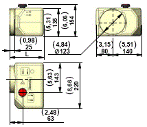
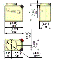
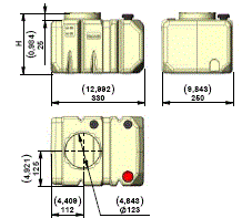
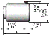
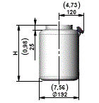
Assembly Kit for Plastic Tank
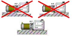
Please make sure the tank and motor are mounted correctly
Oil Tanks for KE - K
Technical Data for Steel Tanks
Steel collar for Tanks
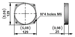
Steel Tanks
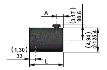
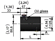
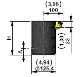
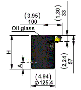
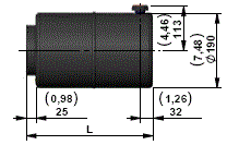
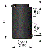
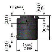
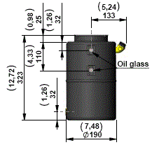
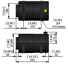
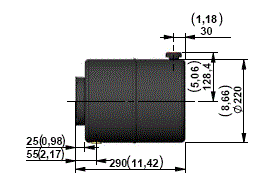
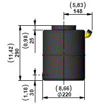
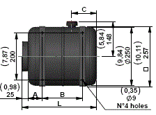
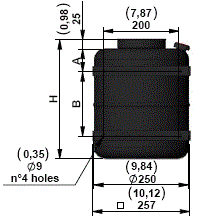
*NOTE
In order to avoid to support the weight of motor by the collar of the tank when the tanks with fi xing brakets are used, it is strongly suggested to support also the central manifold.
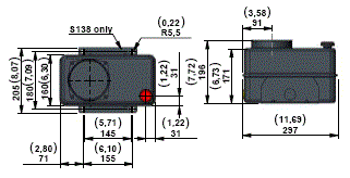
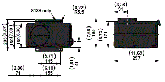
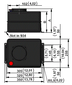
*NOTE
In order to avoid to support the weight of motor by the collar of the tank when the tanks with fi xing brakets are used, it is strongly suggested to support also the central manifold.
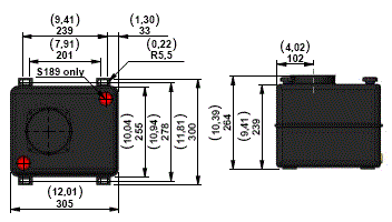
*NOTE
In order to avoid to support the weight of motor by the collar of the tank when the tanks with fixing brakets are used, it is strongly suggested to support also the central manifold.
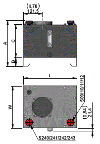

Aluminium Tanks for KE - K
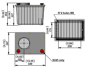
Mounting position
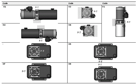
Terminal Box Position for A.C. Motors

Relay Position for D.C. Motors

Oil Cap Position for V1 only

Mounting Brackets
Support for Manifold KE Series

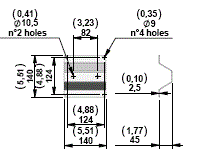
Support for Manifold K Series
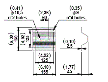


Modular Stackable Elements
Space Modular Block
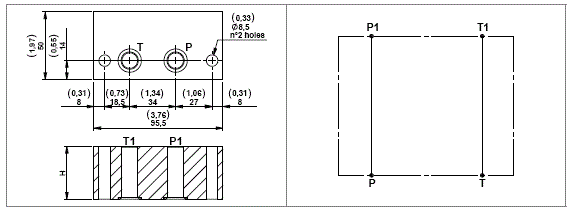
These modular blocks have been designed to have the ability to be assembled as a stack to allow clearence between flanges and motors of different sizes and types. Each block includes 2 OR 3056 gaskets.
Motor IEC71 frame Coupling TR02

Motor IEC80 frame Coupling TR03

Motor IEC90 frame Coupling TR04

Motor IEC100 frame Coupling TR05
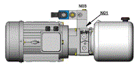
Motor IEC112 frame Coupling TR05
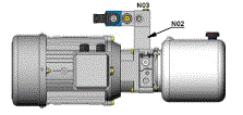
Space Modular Block
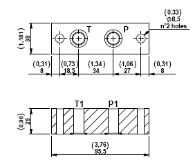
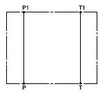
Space Modular Block to fix a compact mounting style electric motor on power module KE type.
This block includes 2 OR 3056 gaskets.
Application Example
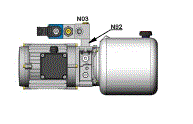
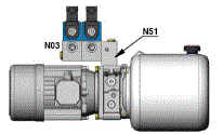
90° Rotation modular block
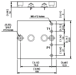
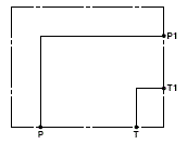
A modular block that is able to have a 90° rotation from our standard OILSISTEM configuration, but keeping the block on the same surface allowing a different position of any other modular block.
Each block includes 2 OR 2056 gaskets.
Application Example
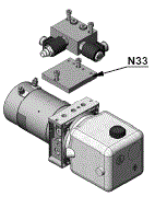
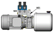
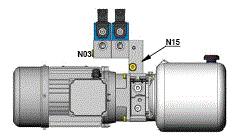
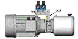
90° modular block allowing horizontal mounting (motor side)
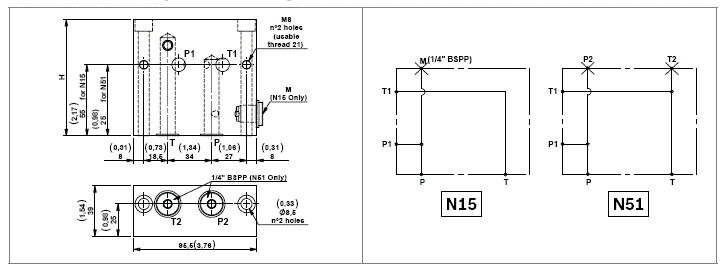
A modular block that is able to turn the standard assembling of 90°, in order to place other manifold blocks over the motor.
The “N15” block has a 1/4” BSPP port for Pressure Gauge.
Each block includes 2 OR 2056 gaskets.
Motor IEC71 frame Coupling TR02
Motor IEC80 frame Coupling TR03
Motor IEC90 frame Coupling TR04
Motor IEC100 frame Coupling TR05
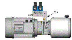
Motor IEC112 frame Coupling TR05
90° modular block allowing horizontal mounting (tank side)
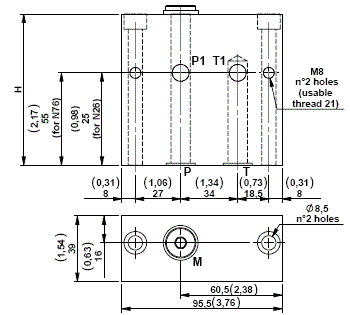

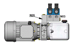
A modular block that is able to turn the standard assembling of 90°, in order to place other blocks over the tank.
The blocks have a 1/4” BSPP port for Pressure Gauge. Each block includes 2 OR 2056 gaskets.
Tank H=134
Tank Diameter Ø190
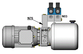
Modular blocks with threaded ports
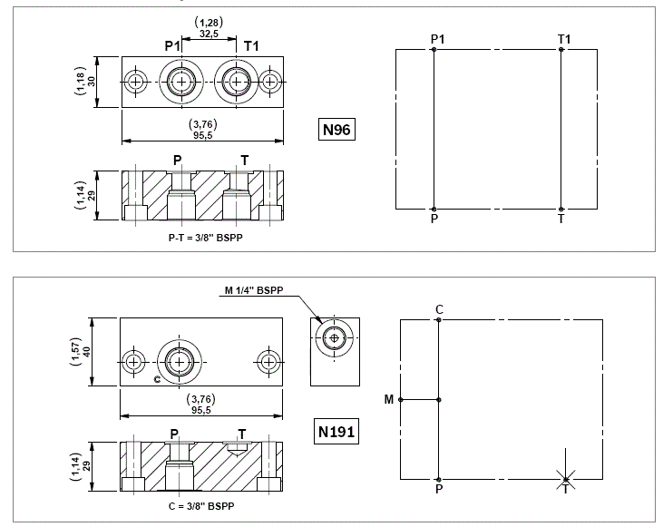
Modular blocks with exit 3/8” BSPP.
Each block includes 2 OR 2056 gaskets.
Modular spacer block with extra “P1” port
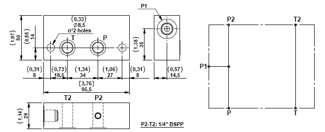
A modular block with an extra port.
Each block includes 2 OR 2056 gaskets.
Modular spacer block with two 1/8” BSPP and two 1/4” BSPP ports
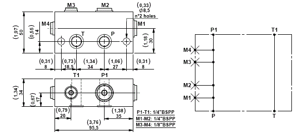
A modular block with 4 extra ports.
Each block includes 2 OR 2056 gaskets.
Modular block with filter on pressure line
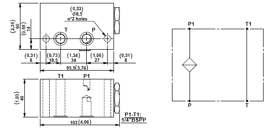
A modular block with a filter on the pressure line. This is recommended for applications where valve may be subjected to contamination.
Each block includes 2 OR 2056 gaskets.
Modular block with filter on the return line
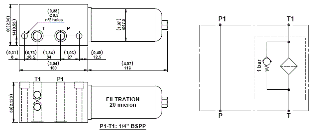
A modular block with filter on return line. This is recommended for applications where valves may be subjected to contamination.
Each block includes 2 OR 2056 gaskets.
Bypass valve set at a pressure of 1 bar.
Modular block for CETOP 3 (2143) configuration valves
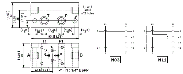
Modular blocks for CETOP 3 (2143) electrovalves for parallel or series circuits.
Each block includes 2 OR 2056 gaskets.
Modular block for CETOP 3 (2143) confi guration valves
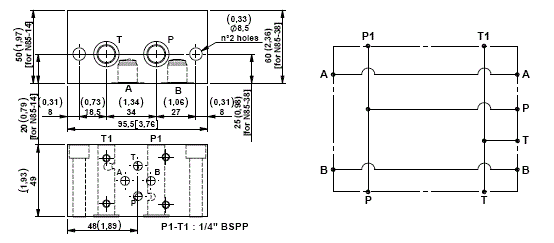
A modular block that is for CETOP 3 (2143) electrovalves for a parallel circuit with ports on the oppsite side of the valve.
Each block includes 2 OR 2056 gaskets.
Modular block for CETOP 3 (2143) configuration valves with side ports
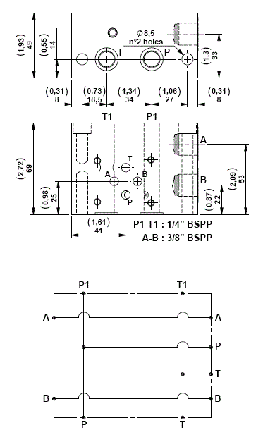
A modular block that is for CETOP 3 (2143) electrovalves for parallel circuit with side device ports on one face.
Each block includes 2 OR 2056 gaskets.
Modular block with poppet type P.O. check valves for CETOP 3 (2143) configuration valves (parallel circuit)
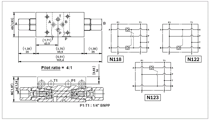
A selection of modular block with P.O. check valves for block CETOP 3 (2143) electrovalves.
Each block includes 2 OR 2056 gaskets.
Possibility to have an OR gasket on the piloting piston for application with low flow.
Sandwich blocks with poppet type “VMD1” relief valves for CETOP 3 (2143) configuration valves
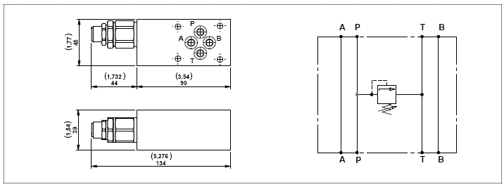
Each block includes 4 OR 108 gaskets.
Sandwich blocks with poppet type “VMD1“ relief valves for CETOP 3 (2143) confi guration valves
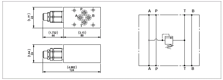
Each block includes 4 OR 108 gaskets.
Sandwich blocks with poppet type “VMD1“ relief valves for CETOP 3 (2143) confi guration valves
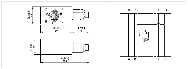
Each block includes 4 OR 108 gaskets.
Sandwich blocks with poppet type “VMD1“ relief valves for CETOP 3 (2143) configuration valves
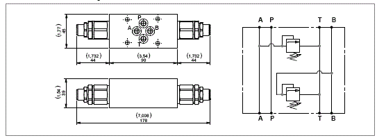
Each block includes 4 OR 108 gaskets.
Sandwich blocks with “ST-CU-06” adjustable flow control valves for CETOP 3 (2143) configuration valves
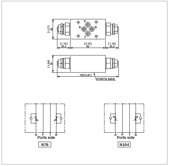
Each block includes 4 OR 108 gaskets.
Sandwich blocks with “ST-CU-06” adjustable fl ow control valves for CETOP 3 (2143) confi guration valves
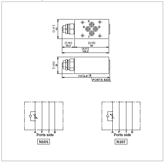
Each block includes 4 OR 108 gaskets.
Sandwich blocks with “ST-CU-06” adjustable fl ow control valves for CETOP 3 (2143) confi guration valves
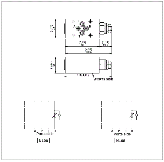
Each block includes 4 OR 108 gaskets.
Sandwich block with ports on “A” and “B” line for CETOP 3 (2143) configuration valves
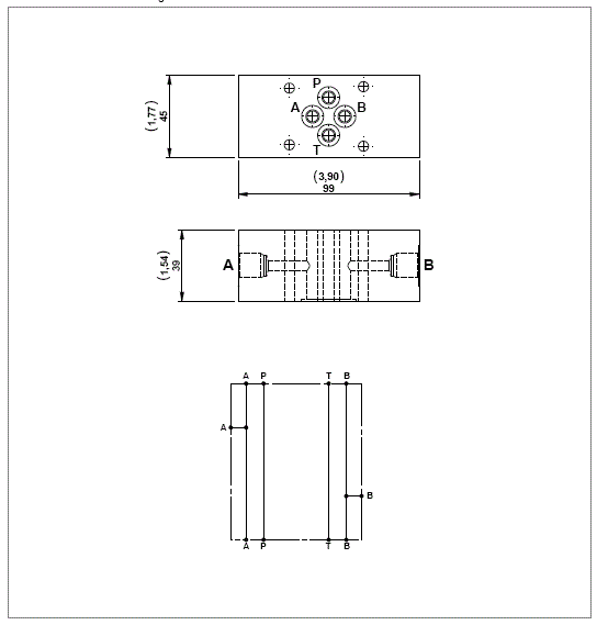
Each block includes 2 OR 2056 gaskets.
Sandwich blocks with overcenter valves for CETOP 3 (2143) configuration valves
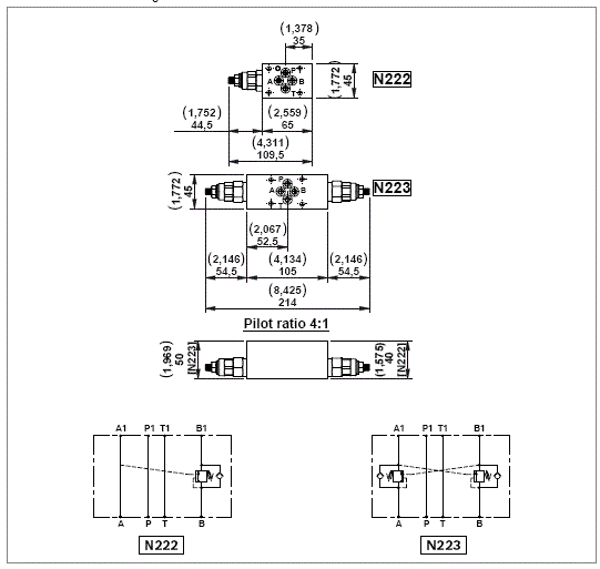
Each block includes 4 OR 108 gaskets.
Modular hand pump manifold block
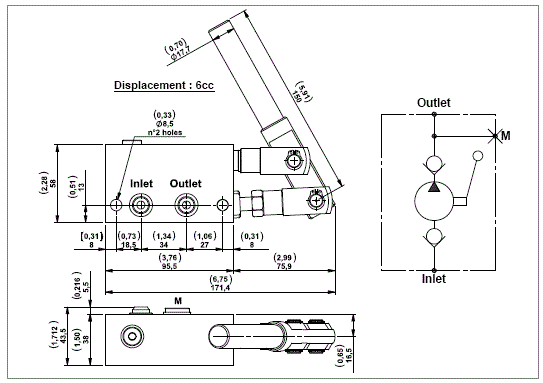
A single acting hand pump usually used for emergency.
Each block includes 5 OR 2050 gaskets.
Lever Kit

CETOP 2143 [Ø6mm (0,24inch)] Solenoid Valves
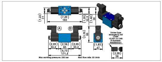


Design
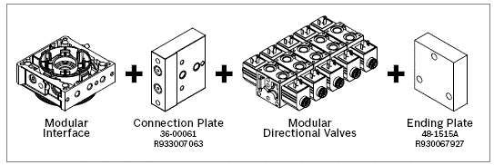
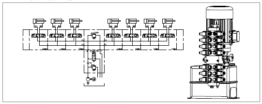
Horizontal Example
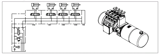
CETOP 2143 [Ø6mm (0,24inch)] Solenoid Valves
NOTE
Please contact our Sales Department for further information.
Modular blocks with two lowering solenoid valves, check valves, and compensated flow control throttle valves (available upon request)
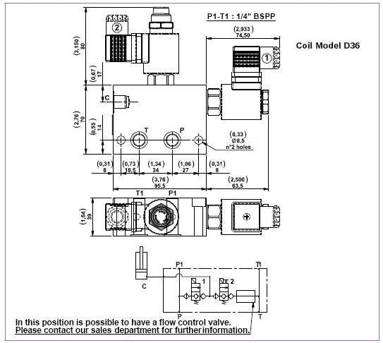
Modular blocks to operate a single acting cylinder in a parallel circuit or a double acting cylinder in regenerative.
Each block includes 2 OR 2056 gaskets.
Minimum voltage required: 90% of nominal.
Coils not included, must be ordered separately.
For the selection of coil model and voltage please refer to page 65.
For the selection of connectors please refer to page 69.
Modular blocks with four way three position solenoid valve. Spool type
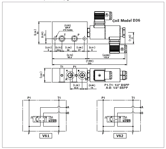
A selection of modular blocks with 4/3 spool type solenoid valve for small double acting cylinders.
Each block includes 2 OR 2056 gaskets.
Minimum voltage required: 90% of nominal.
Coils not included, must be ordered separately.
For the selection of coil model and voltage please refer to page 65.
For the selection of connectors please refer to page 69.
Modular block with four way three position solenoid valve and P.O. check valves on “A” and “B” line
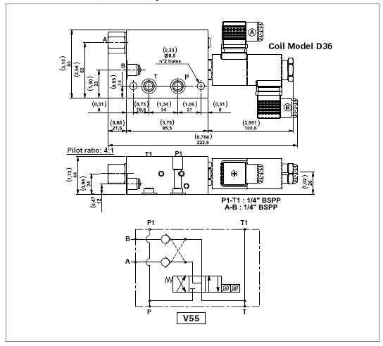
A modular block with 4/3 spool type solenoid valve and P.O. check valves on “A” and “B” line. For small double acting cylinders.
Each block includes 2 OR 2056 gaskets.
Minimum voltage required: 90% of nominal.
Coils not included, must be ordered separately.
For the selection of coil model and voltage please refer to page 65.
For the selection of connectors please refer to page 69.
Modular blocks with double locking solenoid valve
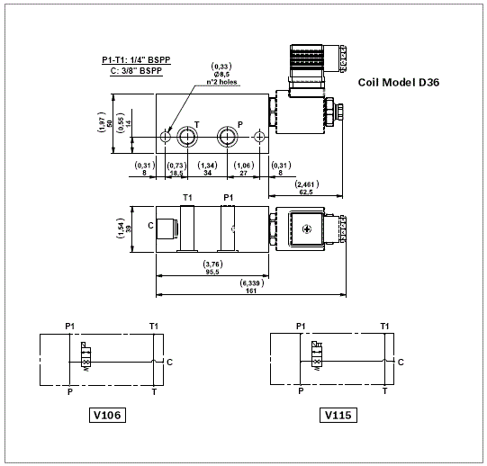
Each block includes 2 OR 2056 gaskets.
Coils not included, must be ordered separately.
For the selection of coil model and voltage please refer to page 65.
For the selection of connectors please refer to page 69.
Accessories
Isolator

Manometer

Cables

Standard Pressure Switches
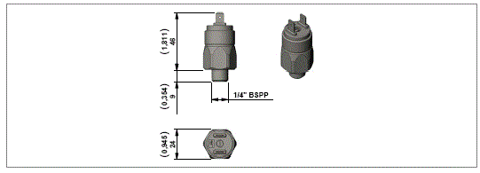
Protective Cap for Standard Pressure Switches
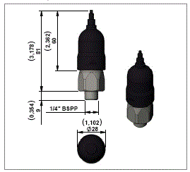
Pressure Switches for manifold A9
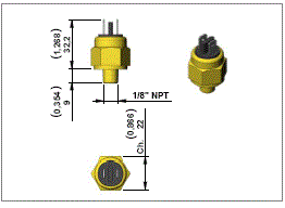
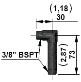
Horizontal Suction, Plastic Pipe


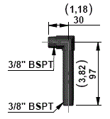
Vertical Suction, Plastic Pipe
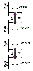
Vertical Suction, Steel Pipe
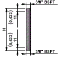
Suction Filter


Horizontal Return, Steel Pipe

Vertical Return, Plastic Pipe
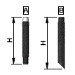
Vertical Return, Steel Pipe


