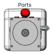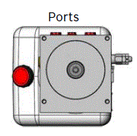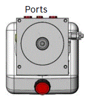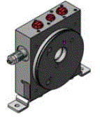
Compact Power Modules - MT Series

MT

Compact power modules MT series
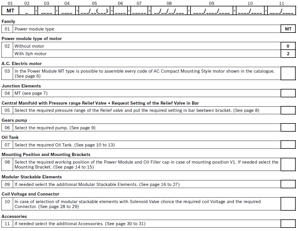
RE18306-04-order

Example of Ordering Details for Compact Power Modules MT

RE18306-04-example-order

Ordering Details for Compact Power Modules with AC Motor

01
02
 
03
 
04
 
05
 
06
 
07
 
08
 
09
 
10
 
11
MT
2
-
847 l
-
TMT
-
MTM01-E/20(150)
-
14AS
-
S435
-
V1/M3
-
MTA01/MTD01/ MT
-
OC/CS
-
ES90/ MN160/ R9.../R9...
Power module type
Power module type of motor
 
AC electric motor
 
Junction element
 
Central manifold with pressure range relief valve + request setting of the relief valve in bar between brackets
 
Gears pump
 
Oil tank
 
Mounting position and mounting brackets
 
Modular stackable elements
 
Coil voltage and connector
 
Accessories

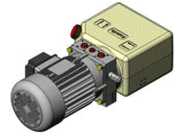
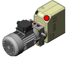
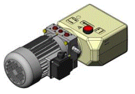
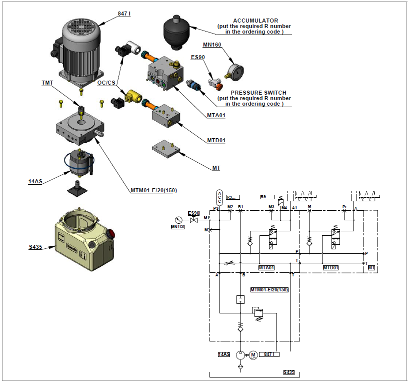
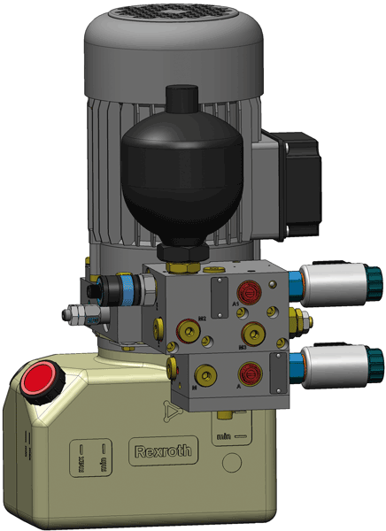
With this catalogue DCOC introduces the „compact power module“ (CPM) MT type developed for clamping operation in Machine Tool. The CPM is an assembly of electric motor, central manifold with valves, pump, oil tank and a few modular elements able to cover the most parts of the schemes needed for this kind of application. The MT model is characterized by low noise level and a very space-saving design due to the direct assembly of the motor and modular elements to the central manifold.


Power module selection

Choose the circuit which meets your application requirements.

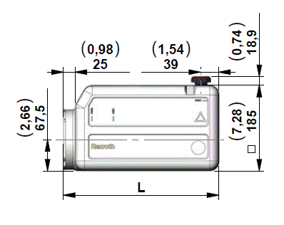
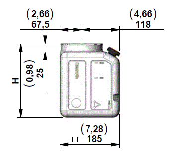
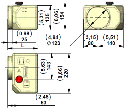
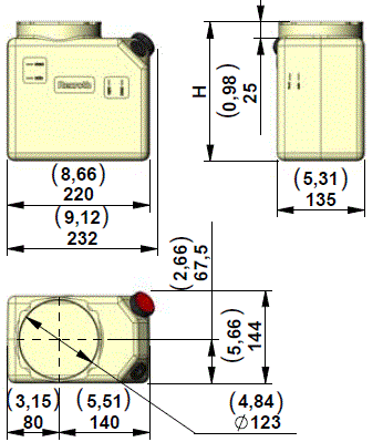
Take note of all dimensions resulting from the basic components chosen for your application.

NOTE

dimensions may vary slightly and should be confirmed by DCOC if the assembly is to be installed in a space with narrow clearance.

The tank capacity and the tank dimensions need to be large enough to assure proper pump suction: there must always be a reserve of oil in the tank when all cylinders are fully extended and avoid overflow when cylinders are fully retracted.

The tank must be evaluated also for best separation of air from oil, and for settling down oil contamination. It should be placed in a space with, at least, natural ventilation and it should permit enough heat dissipation to prevent high fluid temperature.

Select the electric motor by evaluating the power needed and the motor compliance with the heat developed during the expected run time (or „duty cycle“).


Hydraulic fluid for compact power module

Mineral oil based hydraulic fluids suitable for hydraulic systems can be used; they should have physical lubricating and chemical properties as specified by:

  • MINERAL OIL BASED HYDRAULIC FLUIDS HL (DIN 51524 part 1)
  • MINERAL OIL BASED HYDRAULIC FLUIDS HL P(DIN 51524 part 2)

For use of environmentally friendly fluids please consult DCOC.


Fluid viscosity, temperature range of the operating fluid, ambient temperature

The fluid viscosity should remain within the range 10 to 300 cSt (centistokes); recommended 15 to 120 cSt. Permissive cold start viscosity is maximum 2000 cSt . The fluid temperature should remain within the range -15 °C and 70 °C (5 °F and 158 °F).

Ambient temperature -15 °C +40 °C (5 °F and 104 °F).


Fluid cleanliness requirements and maintenance

We recommend a cleanliness of the operating fluid according to ISO 4406 Class 20/18/15 or cleaner.

All components of the hydraulic circuit, including hoses and actuators, must be flushed and cleaned before assembling, because the compact power module has a suction filter only.

The hydraulic fluid should be replaced after the first 50 hours, and then every 1000 hours, or, at least, once a year.


Power module installation

The mounting position is basically un-restricted; just avoid installations that could compromise the pump suction. It is recommended to support the power module on vibration dampening blocks when the mounting structure is expected to vibrate.

Do not assembly the CPM to moving part. Finish required on mounting surface 0.3 mm over 140 mm lenght.


Wiring and starting-up

The wiring between power source and electric motor should be selected in order to avoid excessive voltage drop. It is strictly forbidden to allow the backwards rotation of the pump even at the first starting: to prevent reverse rotation, the wiring polarities must be correctly connected.

NOTE

Caution: when energized, the surface temperature of the electric motor could reach temperature levels of 60 - 80 °C (140 - 176 °F): care should be taken to avoid any accidental contact of people with the motor surface.


A.C. motors

The tolerances on the nominal voltage are:

Three phase motor: 230 - 400V +/-10 %.

Protection degree : IP54 (protection against dust and water splash).

Insulation class: F (155 °C) (311 °F).

All motors are aluminum alloy die cast without painting.


Central manifolds

The Central Manifold is made of extruded aluminum alloy AL 7020 (AlZn4.5Mg UNI9007/1). The validation of the Central Manifold follows a life-test with 250 bar (625 psi) pulsed pressure repeated for 500.000 cycles.


External gear pumps

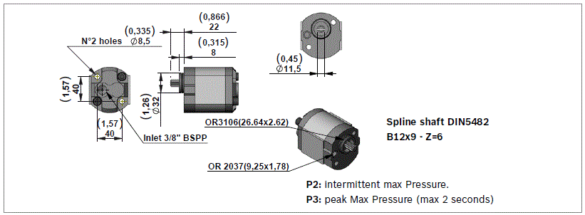
All the pumps are pressure compensated with cast iron covers to guarantee the best efficiency and durability. The splined shaft guarantees a big number of start and stop cycles without failure or wearing. The validation of the pumps follows a life-test at P2 (intermittent max pressure) pulsed pressure repeated for 500.000 cycles.


Oil tanks

In this catalogue you will find a wide selection of plastic tanks available as a standard product. Plastic tanks are obtained in one piece in order to avoid welded parts that are weak points at extreme temperature and vibrations. Plastic tanks are suitable for operating temperature range -15 °C / +70 °C (5 °F / 158 °F).

NOTE

Note: even if the plastic tank mounting system is designed to avoid oil leakage the tank must be securely anchored when subject to shocks and heavy vibrations. Please check that the anchorages do not stress or deform the tank.

Steel tanks are available on request and with a minimum of quantity. Please contact our Sales Department.


Modular stackable elements

Our modular system offers a wide range of standardised elements.

All the Modular Elements are made of extruded aluminum alloy AL 7020 (AlZn4.5Mg UNI9007/1). In the catalogue you will find a selection of the main used models.

The validation of the Modular Elements follows a life-test with 250 bar (625 psi) pulsed pressure repeated for 500.000 cycles.

NOTE: Note: To reduce the complexity of the system and optimize the available space, special Modular Elements can be designed and manufactured following the customers needs. In this case please contact our Sales Department.


European machine directive 2006/42/CE

According to the Machine Directive2006/42/CE, a complete power module, as described in paragraph 15 and made available to the European market, enters into the definition of „partly completed machinery“.

Instead, the power module subassemblies (motor, pump, reservoir, central manifold,...), when not assembled into a complete power pack, are considered „components“ which can be employed in a „machinery“ or a „partly completed machinery“. In this case, the DCOC components and subassemblies must be fitted in compliance with all the relevant technical data sheet applicable to the product, and shall not be operated, adjusted or disassembled before the complete machinery where they are incorporated has been declared to be in compliance with the Machine Directive 2006/42/CE.

NOTE: All the components shown in the catalogue ARE NOT suitable for use in potentially explosive atmosphere.


Technical information

Below you will find the most common equations used in hydraulics:

 
Common Units
Symbols
Equations
Flow
l/min
Q
Q= D×n 1000 ×0.95
Operating pressure
bar
P
P= F 0.1×A
Internal diameter hydraulic cylinder
mm
d
Area of hydraulic cylinder
mm2
A
A= π× d 2 4
Piston force
N
F
Drive shaft
rev/min
n
Power requirement for motor
kW
N
N= P×Q 612
Pump displacement
cm3/rev
D
Torque requirement
Nm
M
M= D×P 62.8×0.87
18306-04_DIM(2024-09-13)

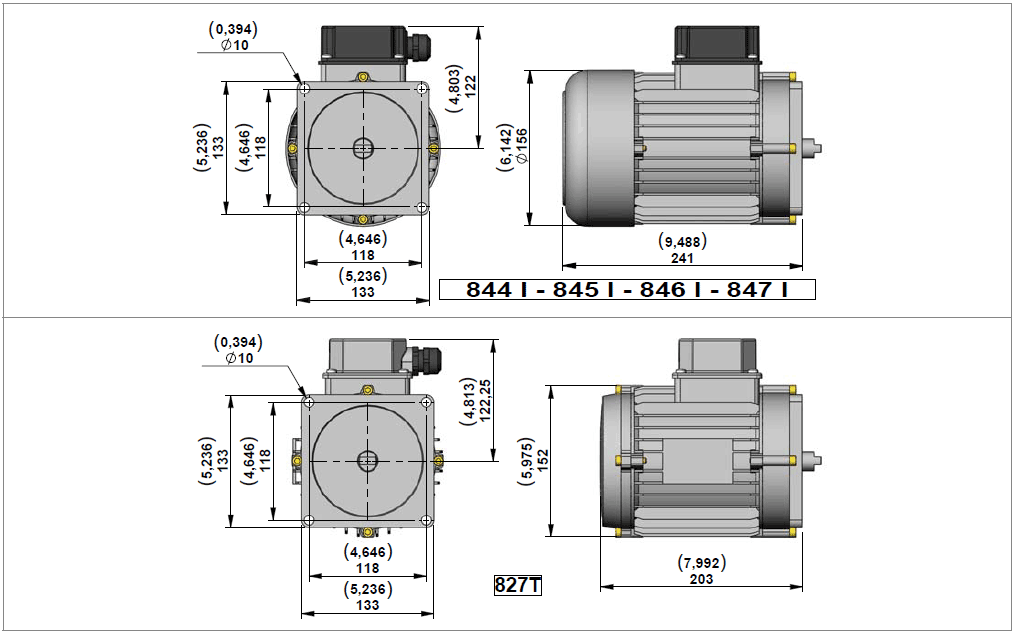
These motors are designed to reduce the overall dimensions and the cost of the junction elements.


Three Phase Current Motors 230/400V 50Hz IP54 Size IEC 80

Code
Type
Material Number
Power (kW)
Power (hp)
Poles
rpm at 50Hz
Duty Cycle
Thermal Switch
844 I
C1622S1457
C1622S1409
0,55
0,75
4
1450
S3 60 %
no
845 I
C1622S1456
R932010924
0,75
1,00
4
1450
S3 60 %
no
846 I
C1622S1453
R932010923
1,10
1,50
4
1450
S3 60 %
no
847 I
C1622S1370
R932000419
1,50
2,00
4
1450
S3 60 %
no
827 T
C1622S1409
R932007620
2,20
3,00
2
2900
S3 15 %
yes

The motors shown in these tables are a selection of our range.

In case of needs of different technical characteristics PLEASE CONTACT OUR SALES DEPARTEMENT.

NOTE: The electric motors shown in this pages are delivered by different certified suppliers. This means the indicated dimensions could change a little, depending on which manufacturer will be assembled. On the CPM the choice of the manufacturer is based on our stock availability.


Junction Elements for A.C. Electric Motor Compact Mounting Style for Power Module Type MT
RE18306-04-junct-element

Junction Elements for manifolds MT

Code
Motor Codes
Size IEC
Type
Material Number
TMT
844 I - 845 I - 846 I - 847 I - 827 T
80
K01K3970TR114
R932011170

MTM01 / MTM01-E

RE18306-04-MTM01_MTM01-E

View Manifold Tank side

RE18306-04-view-manifold-Tank-side
Manifold Code with Relief Valve Pressure Range
Pressure Range bar (psi)
Type
Material Number
MTM01/10
5-100 (72,5-1450)
K397301001
R932007800
MTM01/10
40-200 (580-2901)
K397301002
R932007801
MTM01/10
100-315 (1450-4568)
K397301003
R932007802
MTM01-E/101)
5-100 (72,5-1450)
MTM01-E/101)
40-200 (580-2901)
MTM01-E/101)
100-315 (1450-4568)

NOTE: 1) With type tested safety relief valve according to PED 97/23/EC


Gear Pumps Group 1 with Splined Shaft

RE18306-04-gear-pumps-group1
Code
Displacement cc/rev
Flow at 1400 rpm l/min (gpm)
P2 bar (psi)
P3 bar (psi)
Type
Material Number
11AS
1,25
1,8 (0,48)
250 (3626)
270 (3916)
K01CV640S1260
R932011185
12AS
1,60
2,4 (0,63)
250 (3626)
270 (3916)
K01CV640S1261
R932011186
13AS
2,00
3,0 (0,79)
250 (3626)
270 (3916)
K01CV640S1262
R932011187
14AS
2,50
3,7 (0,98)
250 (3626)
270 (3916)
K01CV640S1263
R932011188
15AS
3,15
4,7 (1,24)
250 (3626)
270 (3916)
K01CV640S1264
R932011189
16AS
3,65
5,5 (1,45)
250 (3626)
270 (3916)
K01CV640S1265
R932011190
17AS
4,20
6,3 (1,66)
230 (3336)
250 (3626)
K01CV640S1266
R932011191
18AS
5,00
7,5 (1,98)
210 (3046)
230 (3336)
K01CV640S1252
R932011192
19AS
5,70
8,5 (2,24)
210 (3046)
230 (3336)
K01CV640S1247
R932011193
20AS
7,40
11,1 (2,93)
180 (2611)
200 (2901)
K01CV640S1249
R932011194

NOTE: All pumps have anti-clockwise rotation.


Flow rate and Pressure

Flow Rate 50 Hz l/min (gpm)
N° poles
RPM
Pump cm³/rev
Motor three phase 230/400V
 
Flow Rate 50 Hz l/min (gpm)
N° poles
RPM
Pump cm³/rev
Motor three phase 230/400V


0,55 kW bar (psi)
0,75 kW bar (psi)
1,1 kW bar (psi)
1,5 kW bar (psi)


2 kW bar (psi)
1,7 (0,45)
4
1400
1,25
198 (2872)
250(3626)
250(3626)
250(3626)
 
3,5 (0,92)
2
2800
1,25
250 (3626)
2,2 (058)
4
1400
1,60
153 (2219)
208(3017)
250(3626)
250(3626)
 
4,4 (1,16)
2
2800
1,60
250 (3626)
2,8 (0,74)
4
1400
2,00
120 (1740)
163(2364)
240(3481)
250(3626)
 
5,6 (1,48)
2
2800
2,00
218 (3162)
3,5 (0,92)
4
1400
2,50
96 (1392)
131(1900)
192(2785)
250(3626)
 
7,0 (1,85)
2
2800
2,50
174 (2524)
4,4 (1,16)
4
1400
3,15
76 (1102)
104(1508)
153(2219)
208(3017)
 
8,8 (2,32)
2
2800
3,15
139 (2016)
5,1 (1,35)
4
1400
3,65
66 (957)
90 (1305)
132(1914)
180(2611)
 
10,2 (2,69)
2
2800
3,65
120 (1740)
5,8 (1,53)
4
1400
4,20
58 (841)
79 (1146)
116(1682)
158(2291)
 
11,7 (3,09)
2
2800
4,20
104 (1508)
7,0 (1,85)
4
1400
5,00
48 (696)
65 (957)
96 (1392)
131(1900)
 
14,0 (3,70)
2
2800
5,00
87 (1262)
7,9 (2,01)
4
1400
5,70
42 (609)
58 (841)
85 (1233)
116(1682)
 
15,9 (4,20)
2
2800
5,70
76 (1102)
10,3 (2,72)
4
1400
7,40
-
44 (638)
65 (943)
89 (1291)
 
20,7 (5,47)
2
2800
7,40
59 (856)

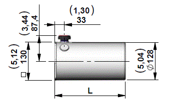
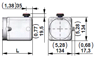
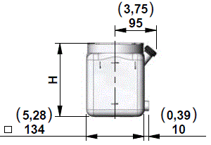
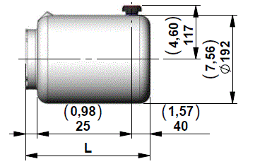
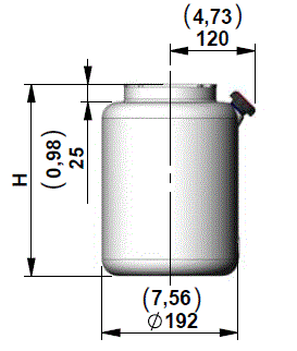
Technical Data for Plastic Tanks

Temperature range
°C °F
-15....+70 °C (5.158 °F)
Materials
 
PE=Polyethylene - PP=Polypropilene
Seal
 
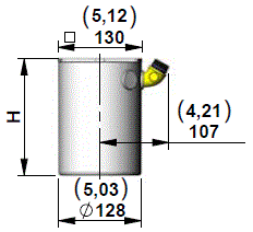
For tanks codes S335-S336-S337-S338-S339-S340-S341-S342 is necessary to use the O-RING Ø112x3 Code: C000191000R-Number:R932000190. For all the other tanks except the codes above is necessary to use the O-RING 4437 (Ø110,7x3,53) Code:110201203000000 - R-Number:R932000188

RE18306-04-1
Code
Tank capacity l (USgal)
Useable capacity l (USgal)
l mm (inch)
Material
Type
Material Number
S335
1,0 (0,26)
0,7 (0,18)
140 (5,51)
PP
K01K3976SE372
R932002035
S336
1,8 (0,48)
1,2 (0,32)
180 (7,09)
 
K01K3976SE373
R932002036
S337
2,5 (0,66)
1,7 (0,45)
240 (9,45)
 
K01K3976SE374
R932002037
S338
3,0 (0,79)
2,3 (0,61)
285 (11,22)
 
K01K3976SE375
R932002038

For this tanks is necessary to use the O-RING Ø112x3 code: C000191000 R-Number: R932000190

RE18306-04-2
Code
Tank capacity l (USgal)
Useable capacity l (USgal)
l mm (inch)
Material
Type
Material Number
S339
1,0 (0,26)
0,6 (0,16)
140 (5,51)
PP
K01K3976SE376
R932007882
S340
1,8 (0,48)
1,1 (0,29)
180 (7,09)
 
K01K3976SE377
R932007883
S341
2,5 (0,66)
1,7 (0,45)
240 (9,45)
 
K01K3976SE378
R932007884
S342
3,0 (0,79)
2,3 (0,61)
285 (11,22)
 
K01K3976SE379
R932007885

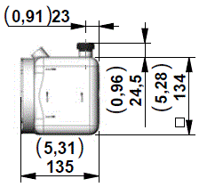
For this tanks is necessary to use the O-RING Ø112x3 code: C000191000 R-Number: R932000190

RE18306-04-3
Code
Tank capacity l (USgal)
Useable capacity l (USgal)
l mm (inch)
Material
Type
Material Number
S246
1,0 (0,26)
0,9 (0,24)
 
PE
K01K3976SE270
R932002016
 

RE18306-04-4
Code
Tank capacity l (USgal)
Useable capacity l (USgal)
l mm (inch)
Material
Type
Material Number
S247
1,8 (0,48)
1,6 (0,42)
170 (6,71)
PE
K01K3976SE271
R932002017
 
S248
2,5 (0,66)
2,2 (0,58)
240 (9,45)
 
K01K3976SE272
R932002018

RE18306-04-5
Code
Tank capacity l (USgal)
Useable capacity l (USgal)
l mm (inch)
Material
Type
Material Number
S249
1,0 (0,26)
0,9 (0,24)
135 (5,31)
PE
K01K3976SE273
R932002019
 
S250
1,8 (0,48)
1,6 (0,42)
170 (6,71)
 
K01K3976SE274
R932002020
S251
2,5 (0,66)
2,2 (0,58)
240 (9,45)
 
K01K3976SE275
R932002021

RE18306-04-6
Code
Tank capacity l (USgal)
Useable capacity l (USgal)
Lmm(inch)
Material
Type
Material Number
S343
5,0 (1,32)
3,8 (1,00)
230 (9,05)
PE
K01K3976SE380
R932002039
S331
5,0 (1,32)
3,8 (1,00)
230 (9,05)
PE Black
K01K3976SE368
R932007872
S413
7,0 (1,85)
5,5 (1,45)
310 (12,20)
PE
K01K3976SE439
R932007873
S414
7,0 (1,85)
5,5 (1,45)
310 (12,20)
PE Black
K01K3976SE440
R932007874
S415
8,0 (2,11)
6,5 (1,72)
335 (13,19)
PE
K01K3976SE441
R932006036
S416
8,0 (2,11)
6,5 (1,72)
335 (13,19)
PE Black
K01K3976SE442
R932007875
S316
9,0 (2,38)
7,3 (1,93)
365 (14,37)
PE
K01K3976SE351
R932002031
S314
9,0 (2,38)
7,3 (1,93)
365 (14,37)
PE Black
K01K3976SE451
R932007876
S417
12,0 (3,17)
10,0 (2,64)
495 (19,50)
PE
K01K3976SE443
R932006768
S418
12,0 (3,17)
10,0 (2,64)
495 (19,50)
PE Black
K01K3976SE444
R932007877

RE18306-04-7
Code
Tank capacity l (USgal)
Useable capacity l (USgal)
Lmm(inch)
Material
Type
Material Number
S344
5,0 (1,32)
3,5 (0,92)
230 (9,05)
PE
K01K3976SE381
R932002040
S332
5,0 (1,32)
3,5 (0,92)
230 (9,05)
PE Black
K01K3976SE369
R932008240
S419
7,0 (1,85)
5,5 (1,45)
310 (12,20)
PE
K01K3976SE445
R932007879
S420
7,0 (1,85)
5,5 (1,45)
310 (12,20)
PE Black
K01K3976SE446
R932007880
S421
8,0 (2,11)
6,5 (1,72)
335 (13,19)
PE
K01K3976SE447
R932006037
S422
8,0 (2,11)
6,5 (1,72)
335 (13,19)
PE Black
K01K3976SE448
R932007881
S315
9,0 (2,38)
7,3 (1,93)
365 (14,37)
PE
K01K3976SE350
R932002030
S313
9,0 (2,38)
7,3 (1,93)
365 (14,37)
PE Black
K01K3976SE348
R932002029
S423
12,0 (3,17)
10,0 (2,64)
495 (19,50)
PE
K01K3976SE349
R932006038
S424
12,0 (3,17)
10,0 (2,64)
495 (19,50)
PE Black
K01K3976SE450
R932006278

RE18306-04-8
Code
Tank capacity l (USgal)
Useable capacity l (USgal)
Lmm(inch)
Material
Type
Material Number
S395
3,0 (0,79)
1,7 (0,45)
140 (5,51)
PE
K01K3976SE470
R932007903
 
S396
3,7 (0,98)
2,2 (0,58)
165 (6,50)
 
K01K3976SE471
R932007904
S392
5,0 (1,32)
3,1 (0,82)
215 (8,46)
 
K01K3976SE464
R932007365
S394
8,4 (2,22)
5,5 (1,45)
340 (13,39)
 
K01K3976SE466
R932007435
S397
12,7 (3,35)
8,4 (2,2)
500 (19,68)
 
K01K3976SE472
R932007905
S395
3,0 (0,79)
1,7 (0,45)
140 (5,51)
PE
K01K3976SE470
R932007903
S396
3,7 (0,98)
2,2 (0,58)
165 (6,50)
 
K01K3976SE471
R932007904
S392
5,0 (1,32)
3,1 (0,82)
215 (8,46)
 
K01K3976SE464
R932007365
S394
8,4 (2,22)
5,5 (1,45)
340 (13,39)
 
K01K3976SE466
R932007435
S397
12,7 (3,35)
8,4 (2,2)
500 (19,68)
 
K01K3976SE472
R932007905

RE18306-04-10
Code
Tank capacity l (USgal)
Useable capacity l (USgal)
Lmm(inch)
Material
Type
Material Number
S434
3,0 (0,79)
1,7 (0,45)
140 (5,51)
PE
K01K3976SE478
R932007910
S435
3,7 (0,98)
2,2 (0,58)
165 (6,50)
 
K01K3976SE479
R932007911
S436
5,0 (1,32)
3,1 (0,82)
215 (8,46)
 
K01K3976SE480
R932007912
S437
8,4 (2,22)
5,5 (1,45)
340 (13,39)
 
K01K3976SE481
R932007913
S438
12,7 (3,35)
8,4 (2,2)
500 (19,68)
 
K01K3976SE482
R932007914

RE18306-04-11
Code
Tank capacity l (USgal)
Useable capacity l (USgal)
Lmm(inch)
Material
Type
Material Number
S374
5,0 (1,32)
4,0 (1,06)
219 (8,62)
PE
K01K3976SE415
R932002042
 
S376
7,0 (1,85)
5,4 (1,43)
271 (10,67)
 
K01K3976SE417
R932002044
S378
8,0 (2,11)
6,6 (1,74)
323 (12,72)
 
K01K3976SE419
R932002046
S380
11,0 (2,91)
9,6 (2,54)
453 (17,83)
 
K01K3976SE421
R932002048

RE18306-04-12
Code
Tank capacity l (USgal)
Useable capacity l (USgal)
Lmm(inch)
Material
Type
Material Number
S375
5,0 (1,32)
4,0 (1,06)
219 (8,62)
PE
K01K3976SE416
R932002043
 
S377
7,0 (1,85)
5,4 (1,43)
271 (10,67)
 
K01K3976SE418
R932002045
S379
8,0 (2,11)
6,6 (1,74)
323 (12,72)
 
K01K3976SE420
R932002047
S381
11,0 (2,91)
9,6 (2,54)
453 (17,83)
 
K01K3976SE422
R932002049

Assembly Kit for Plastic Tank - MT
RE18306-04-13 RE18306-04-13
Oil Tank
Code for MT
Material Number
S335 - S336 - S337 - S338 - S339 - S340 S341 -S342
K2501VT016
R932007391
S246 - S247 - S248 - S249 - S250 - S251
K2501VT025
R932011181
S413 - S414 - S419 - S420 - S415 - S416 - S421 - S422 - S332 - S344 - S313 - S315 - S343 - S331 - S316 - S314 - S374 - S375 - S376 - S377 - S378 - S379 - S380 - S381 - S417 - S418 - S423 - S424 - S395 - S396 - S392 - S394 - S397 - S434 - S435 - S436 - S437 - S438
K2501VT015
R932008244

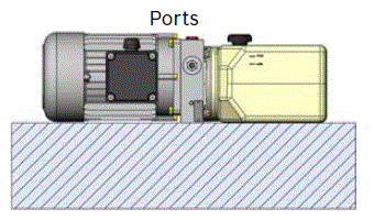
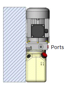
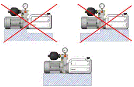
Please make sure that the tank and motor are mounted correctly


RE18306-04-14 RE18306-04-21 RE18306-04-15 RE18306-04-16 RE18306-04-22
Mounting position
 
Code
Image
01
1
V1
2
L
3
T
4
R
5

RE18306-04-17 RE18306-04-23 RE18306-04-18 RE18306-04-24
Terminal Box Position for A.C. Motors
 
Code
Image
6
M2
7
M3
8
M4
9

RE18306-04-19 RE18306-04-25 RE18306-04-20 RE18306-04-26
Oil Cap Position for V1 only
 
Code
Image
10
LU
11
LO
12
LP
13

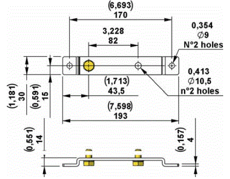
Support for Manifold MT series

RE18306-04-27 RE18306-04-28
Code
Central manifold
Type
Material number
 
 
GMT
MT
K01K331528000
R932011175

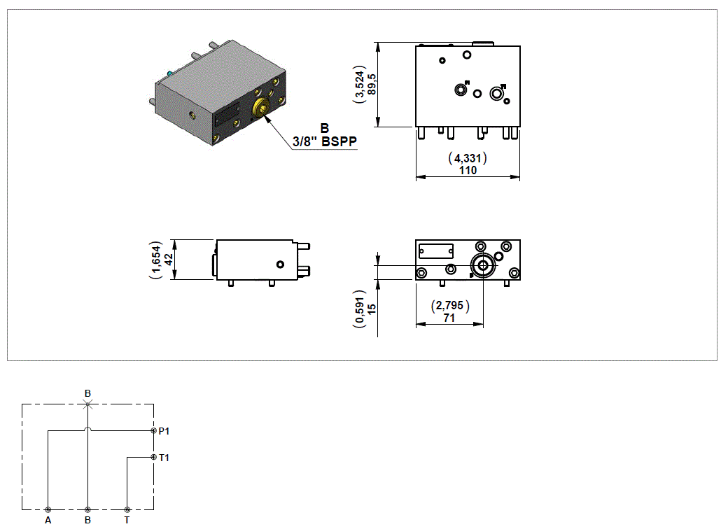
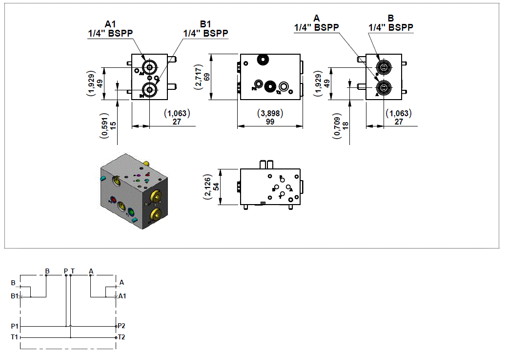
Modular Stackable Element MTA01

RE18306-04-modular-stack-ele-MTA01
Code
Description
Max working pressure bar (psi)
Max flow l/min (gpm)
Type
Material number
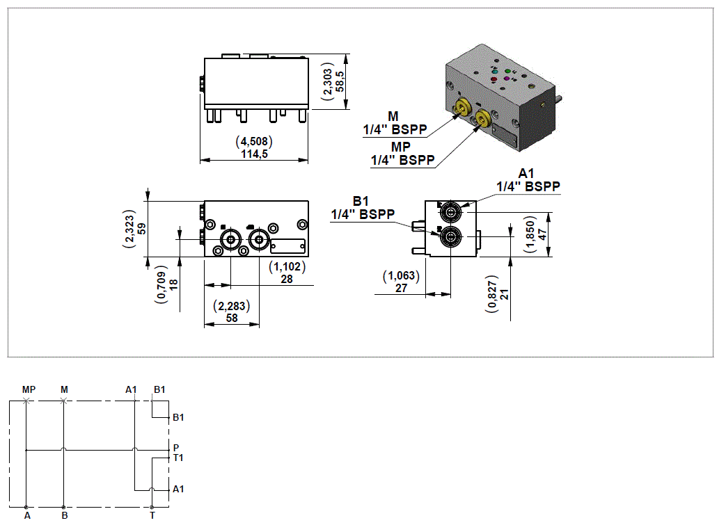
MTA01
Kit MTA01 Modular block
250 (3626)
12,0 (3,17)
0985900017
R932008163

NOTE: Use coil model K4 For 3/2 KSDE solenoid valve check data sheet RE18136.


Mounting Example

RE18306-04-mount-example1

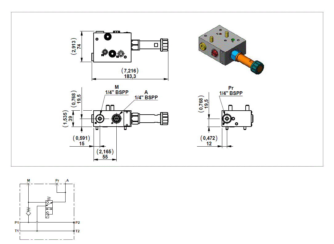
Modular Stackable Element MTA02

RE18306-04-modular-stack-ele-MTA02
Code
Description
Max working pressure bar (psi)
Max flow l/min (gpm)
Type
Material number
MTA02
Kit MTA02 Modular block
250 (3626)
12,0 (3,17)
0985900021
R932010931

NOTE: Use coil model K4 For 3/2 KSDE solenoid valve check data sheet RE18136.


Mounting Example

RE18306-04-mount-example2

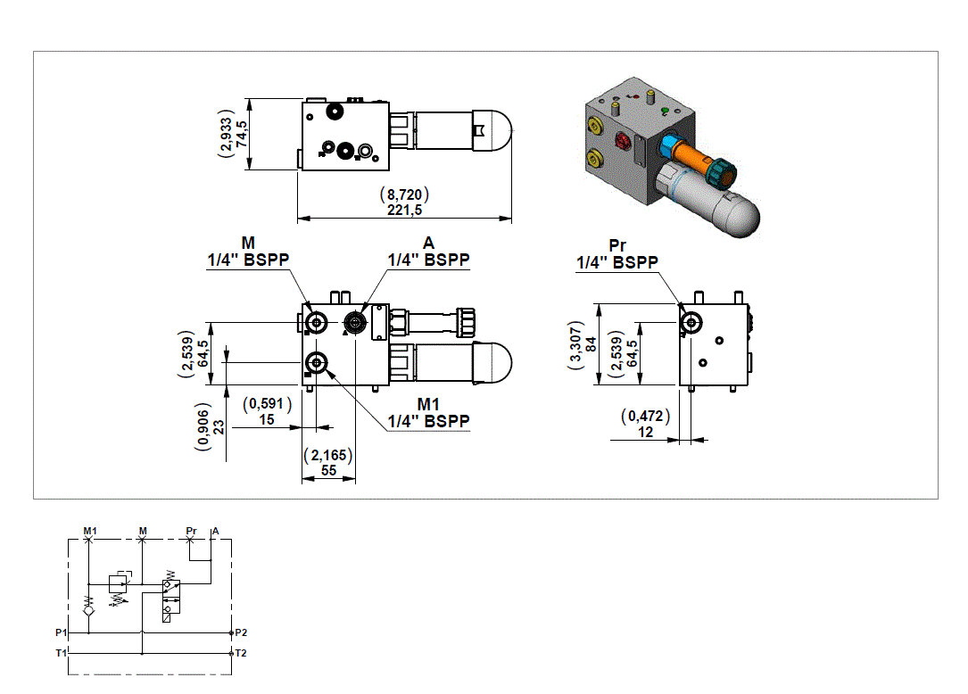
Modular Stackable Element MTA03

RE18306-04-modular-stack-ele-MTA03
Code
Description
Max working pressure bar (psi)
Max flow l/min (gpm)
Type
Material number
MTA03
Kit MTA03 Modular block
250 (3626)
20,0 (5,28)
0985900011
R932007989

Mounting Example

RE18306-04-mount-example3

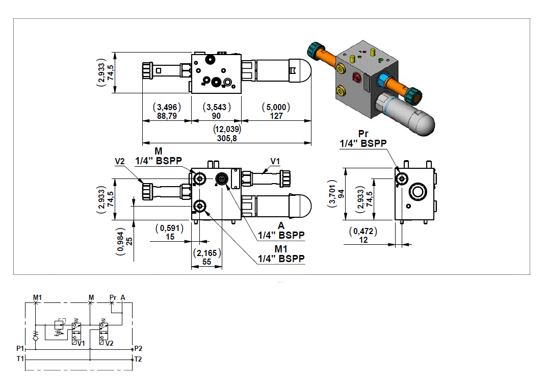
Modular Stackable Element MTA04

RE18306-04-modular-stack-ele-MTA04
Code
Description
Max working pressure bar (psi)
Max flow l/min (gpm)
Type
Material number
MTA04
Kit MTA04 Modular block
250 (3626)
20,0 (5,28)
0985900018
R932008172

Mounting Example

RE18306-04-mount-example4

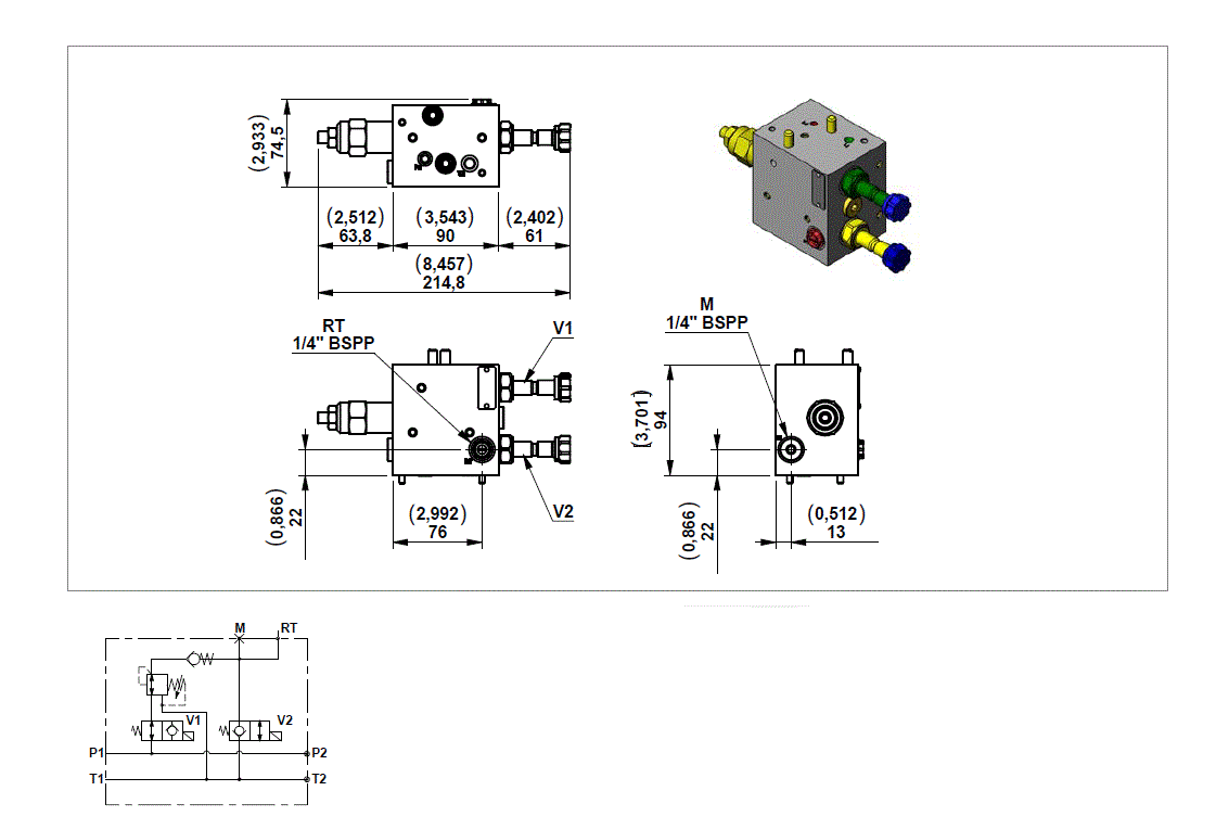
Modular Stackable Element MTD01

RE18306-04-modular-stack-ele-MTD01
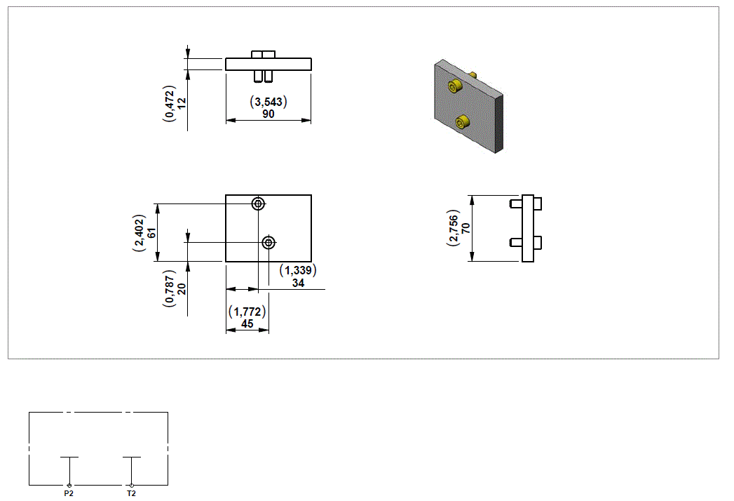
<>
Code
Description
Max working pressure bar (psi)
Max flow l/min (gpm)
Type
Material number
MTD01
Kit MTD01 Modular block
250 (3626)
12,0 (3,17)
0985900001
R932007956

NOTE: Use coil model K4 For 3/2 KSDE solenoid valve check data sheet RE18136.


Mounting Example

RE18306-04-mount-example5

Modular Stackable Element MTD02

RE18306-04-modular-stack-ele-MTD02
Code
Description
Max Working Pressure bar (psi)
Max Flow l/min (gpm)
Pressure Stage
Type
Material Number
MTD02/1
Kit MTD02/1 Modular block with pressure reducing valve
250 (3626)
12,0 (3,17)
Pressure setting up to 100 bar (1450)
0985900002
R932007965
MTD02/2
Kit MTD02/2 Modular block with pressure reducing valve
250 (3626)
12,0 (3,17)
Pressure setting up to 210 bar (3046)
0985900003
R932007966

NOTE: Use coil model K4 For 3/2 KSDE solenoid valve check data sheet RE18136. For KRD pressure reducing valve check data sheet RE18111.


Mounting Example

RE18306-04-mount-example6

Modular Stackable Element MTD03

RE18306-04-modular-stack-ele-MTD03
Code
Description
Max Working Pressure bar (psi)
Max Flow l/min (gpm)
Pressure Stage
Type
Material Number
MTD03/1
Kit MTD03/1 Modular block with pressure reducing valve
250 (3626)
12,0 (3,17)
Pressure setting up to 100 bar (1450)
0985900005
R932007974
MTD03/2
Kit MTD03/2 Modular block with pressure reducing valve
250 (3626)
12,0 (3,17)
Pressure setting up to 210 bar (3046)
0985900006
R932007975

NOTE: Use coil model K4 For 3/2 KSDE solenoid valve check data sheet RE18136. For KRD pressure reducing valve check data sheet RE18111.


Mounting Example

RE18306-04-mount-example7

Modular Stackable Element MTD04

RE18306-04-modular-stack-ele-MTD04
Code
Description
Max Working Pressure bar (psi)
Max Flow l/min (gpm)
Pressure Stage
Type
Material Number
MTD04/1
Kit MTD04/1 Modular block with pressure reducing valve
250 (3626)
12,0 (3,17)
Pressure setting up to 100 bar (1450)
0985900008
R932007983
MTD04/2
Kit MTD04/2 Modular block with pressure reducing valve
250 (3626)
12,0 (3,17)
Pressure setting up to 210 bar (3046)
0985900009
R932007984

NOTE: Use coil model K4 For 3/2 KSDE solenoid valve check data sheet RE18136. For KRD pressure reducing valve check data sheet RE18111.


Mounting Example

RE18306-04-mount-example8

Modular Stackable Element MTD08

RE18306-04-modular-stack-ele-MTD08
Code
Description
Max working pressure bar (psi)
Max flow l/min (gpm)
Type
Material number
MTD08
Kit MTD08 Modular block
250 (3626)
20,0 (5,28)
0985900012
R932007997

Mounting Example

RE18306-04-mount-example9

Modular Stackable Element RT60

RE18306-04-modular-stack-ele-RT60
Code
Description
Max Working Pressure bar (psi)
Max Flow l/min (gpm)
Pressure Stage
Type
Material Number
RT60/05
Kit RT60/05 Modular block with pressure reducing valve
250 (3626)
20,0 (5,28)
Pressure setting up to 10-50 bar (145-725)
0985900020
R932008367
RT60/08
Kit RT60/08 Modular block with pressure reducing valve
250 (3626)
20,0 (5,28)
Pressure setting up to 28-80 bar (406-1160)
0985900019
R932008361

NOTE: Use Coil Model S8


Mounting Example

RE18306-04-mount-example10

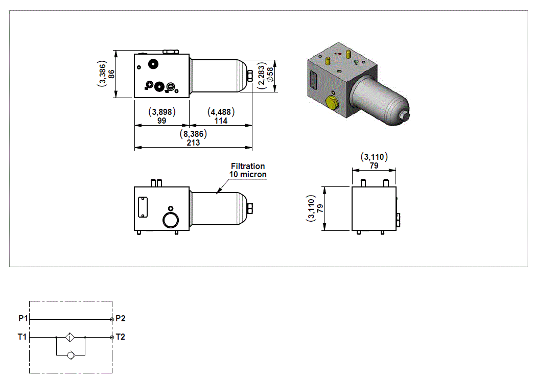
Modular Stackable Element MTF01

RE18306-04-modular-stack-ele-MTF01
Code
Description
Max working pressure bar (psi)
Max flow l/min (gpm)
Type
Material number
MTF01
Kit MTF01 Modular block
250 (3626)
15,0 (3,96)
0985900022
R932011139

Mounting Example

RE18306-04-mount-example11

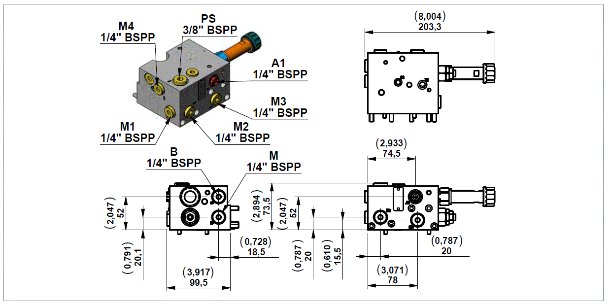
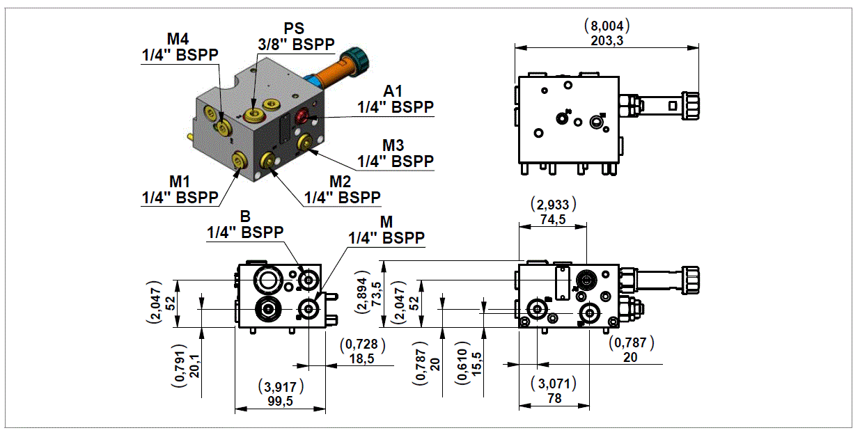
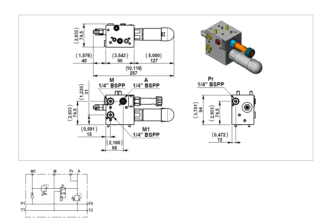
Modular Stackable Element MT

RE18306-04-modular-stack-ele-MT
Code
Description
Type
Material number
MT
Kit MT Closing plate
0985900016
R932008159

Mounting Example

RE18306-04-mount-example12

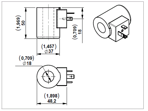
K4

RE18306-04-K4
Code
Connection
Voltage
Material Number
OB
03-pin (2+PE) DIN EN 175301-803
12 V
R900991678
OC
03-pin (2+PE) DIN EN 175301-803
24 V
R900991121

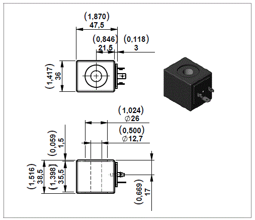
S8

RE18306-04-S8

Only for modular block RT60

Code
Connection
Voltage
Material Number
OB
DIN 43650 - ISO 4400
12 V
R901090821
OC
DIN 43650 - ISO 4400
24 V
R901083065

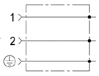
CONNECTOR IP67 - EN175000 (DIN 4350-A) / ISO 4400

RE18306-04-connector-IP67
Ambient temperature - Standard
°C (°F)
- 20 to + 60 °C (-4 to +140°F) °F
Type of protection according to DIN 40050
 
IP67 with cable socket mounted and locked
Operating voltage
V
Choose the proper ordering code according to the circuit V
Maximum operating current - Standard
A
16 A
Number of pins
 
2 + PE
Clamping range for cables having an outer diameter of
mm (in)
5, up to 10 mm (0,2 up to 0,4 inch)
Cable entry
 
Pg9 / Pg11 (unified)
Maximum cable cross-section
mm² (in²)
1.5 mm² (0,002 in²)

Standard Circuit

RE18306-04-std-circ
Code
Colour
Cable entry
Type
Material Number
WC
Without Connector


CS
black
Pg9 / Pg11
OD016901000000
R934004344

Isolator

RE18306-04-isolator
Code
Description
Type
Material Number
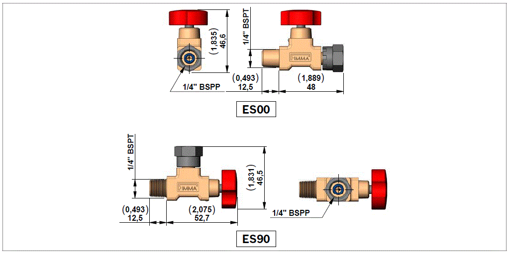
ES00
Straight isolator
EM 14
R932500182
ES90
90° isolator
EM 14 T
R932500184

Manometer

RE18306-04-manometer
Code
Description
Pressure range bar (psi)
Type
Material Number
MN100
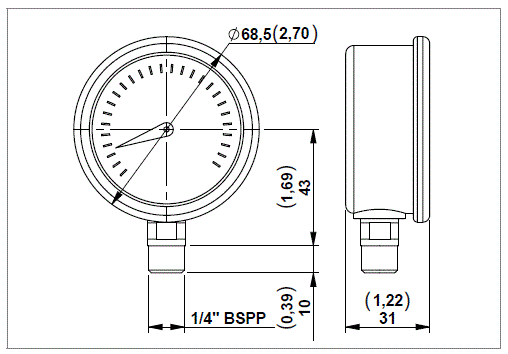
Pressure gauge
0-100 (0-1450)
C163017000
R932000582
MN160
Pressure gauge
0-160 (0-2320)
C163018000
R932000583
MN250
Pressure gauge
0-250 (0-3626)
C163019000
R932000584
MN315
Pressure gauge
0-315 (0-4568)
C163020000
R932000585

Pressure Switches

RE18306-04-pressure-switches

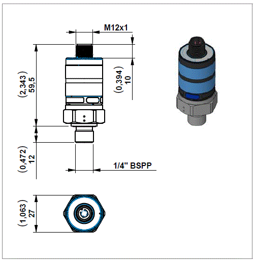
NOTE: If you need a electronic pressure switch please refer to the data sheet RE 30279


Accumulator
RE18306-04-accumulator

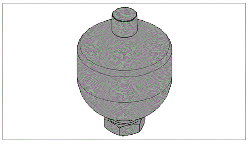
NOTE: If you need an diaphragm-type accumulator please refer to the data sheet RE 50150