Compact Directional Valves - Non-compensated and Post-compensated - Directional elements EDD Series

EDD-XZ

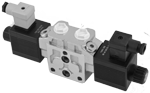
Valve elements with solenoid operated directional spool. Control spools directly operated by solenoids with removable coils.

In the de-energized condition, the control spool is held in the central position by return springs.

Wet pin tubes for DC coils, with push rod for mechanical override; zinc plated surface.

Coils can be rotated 180° around the tube; they can be energized by AC current throught special connection with rectifier (RAC).

Manual override (push-button, screw type) available as option.

Different plug-in connectors available: see ordering details.

Size 8

Series 00

Maximum pressure (pump side) 310 bar (4500 psi)

Maximum pressure (actuator side) 380 bar (5500 psi)

Maximum flow 80 l/min (21.1 gpm)

Port connections G 1/2 - SAE10 - Flangeable

RE18301-12-order

Symbols

RE18301-12-sym

Secondary valves possible configurations

RE18301-12-sec-valves

Flangeable version =M

RE18301-12-flange-version
A
B
C
D
E
F
G
H
I
J
K
L
20 bar
30 bar
40 bar
50 bar
60 bar
70 bar
80 bar
90 bar
100 bar
110 bar
120 bar
130 bar
290 psi
435 psi
580 psi
725 psi
870 psi
1015 psi
1160 psi
1305 psi
1450 psi
1595 psi
1740 psi
1885 psi
M
N
O
P
Q
R
S
T
U
V
W
X
140 bar
150 bar
160 bar
170 bar
180 bar
190 bar
200 bar
210 bar
220 bar
230 bar
240 bar
250 bar
2030 psi
2175 psi
2320 psi
2465 psi
2611 psi
2756 psi
2901 psi
3046 psi
3191 psi
3336 psi
3481 psi
3626 psi
1)
The required hydraulic symbol and spool variant can be chosen by consulting page 2.
2)
The use of the secondary valve in one ports implies the use of secondary valve in both ports.
3)
The relief direct acting valve have a maximum flow capacity of 30 l/min (7.93 gpm).For the characteristic curves see data sheet RE18329-11.
4)
For connectors ordering code see data sheet RE 18325-90.
5)
For the Characteristic curves see data sheet RE18329-51.

Spool variant

RE18301-12-spool
RE18301-12-functional

The sandwich plate design directional valve elements D8_5 are compact direct operated solenoid valves which control the start, the stop and the direction of the oil flow. These elements basically consist of a stackable housing (1) with a control spool (2), one or two solenoids (5), and one or two return springs (4). The spring chambre are connected to the tank port. When the coil is energized, the spool (2) travels and oil is pushed to tank from one of the spring chambers: if the cross section of the orifices changes, the switching time changes as well. Three orifice sizes are available: smaller orifice results in longer switching time, even though the actual time is dependent upon pressure, flow and viscosity.When energized, the force of the solenoid (5) pushes the control spool (2) from its neutral-central position to the required position, and the required flow from P to A (with B to T), or P to B (with A to T) is achieved. Once the solenoid is de-energized, the return spring (4) pushes the spool thrust washer (3) back against the housing and the spool returns in its neutral-central position. Each coil is fastened to the solenoid tube by a ring nut (6). A pin (7) allows to push the spool (2) in emergency conditions, when the solenoid cannot be energized, like in case of voltage shortage. The secondary cartridge valves are designed for quick response and stable pressure control (8); they also incorporate a reverse flow check for anti-cavitation

Code
Voltage [V]
Connector type
Coil description
Marking
Coil Mat no.
OB 01
12 DC
EN 175301-803(Ex. DIN 43650)
C4801 12DC
12 DC
R933000063
OB 03
12 DC
AMP JUNIOR
C4803 12DC
12 DC
R933000065
OB 07
12 DC
DEUTSCH DT 04-2P
C4807 12DC
12 DC
R933000068
OB 31
12 DC
Cable 350 mm long
C4831 12DC
12 DC
R933000064
AD 01
13 DC
EN 175301-803(Ex. DIN 43650)
C4801 13DC
13 DC
R933000069
AD 07
13 DC
DEUTSCH DT 04-2P
C4807 13DC
13 DC
R933000073
OC 01
24 DC
EN 175301-803(Ex. DIN 43650)
C4801 24DC
24 DC
R933000076
OC 03
24 DC
AMP JUNIOR
C4803 24DC
24 DC
R933000071
OC 07
24 DC
DEUTSCH DT 04-2P
C4807 24DC
24 DC
R933000075
OC 31
24 DC
Cable 350 mm long
C4831 24DC
24 DC
R933000070
AC 01
27 DC
EN 175301-803(Ex. DIN 43650)
C4801 27DC
27 DC
R933000077
AC 07
27 DC
DEUTSCH DT 04-2P
C4807 27DC
27 DC
R933000074
OD 01
48 DC
EN 175301-803(Ex. DIN 43650)
C4801 48DC
48 DC
R933000078
OV 01
24 RAC
EN 175301-803(Ex. DIN 43650)
C4801 21.5DC
21.5 DC
R933000079
OW 01
110 RAC
EN 175301-803(Ex. DIN 43650)
C4801 98DC
98 DC
R933000080
OZ 01
230 RAC
EN 175301-803(Ex. DIN 43650)
C4801 207DC
207 DC
R933000081
General:
Valve element with 2 solenoids:
  • 3.00 kg (6.61 lbs)
Valve element with 1 solenoid:
  • 2.35 kg (5.18 lbs)
Ambient temperature:
  • –20....+50 (-4.... +122) (NBR seals)
Hydraulic:
Maximum pressure at P:
  • 310 bar (4500 psi)
Maximum pressure at A and B ports:
  • 380 bar (5500 psi)
Maximum pressure at T:
  • 250 bar (3625 psi)
Maximum inlet flow:
  • 80 l/min (21.1 gpm)
Hydraulic fluidGeneral properties: it must have physical lubricating and chemical properties suitable for use in hydraulic systems such as, for example:
  • Mineral oil based hydraulic fluids HL (DIN 51524 part 1). For use of environmentally acceptable fluids (vegetable or polyglycol base) please consult us.
Fluid Temperature:
  • –20....+80°C (-4.... +176°F) (NBR seals)
Permissible degree of fluid contamination:
  • ISO 4572: βₓ≥75 X=12...15 NAS 1638: class 9
Viscosity range:
  • 5....420 mm²/s
Electrical:
Voltage type:
  • DC (AC only with RAC connection)
Voltage tolerance (nominal voltage):
  • -10 .... +10%
Duty:
  • Continuous, with ambient temperature ≤ 50°C (122°F)
Coil wire temperature not to be exceeded:
  • 150°C (302°F)
Insulation class:
  • H
Compliance with:
  • Low Voltage Directive LVD 73/23/EC (2006/95/EC), 2004/108/EC
Coil weight with connection EN 175301-803:
  • 0.5 kg (1.1 lbs)
Voltage:
  • 12 V
  • 13 V
  • 24 V
  • 27 V
  • 48 V
  • 24 V +RAC (21,5)
  • 110 V +RAC (98)
  • 230 V +RAC (207)
Voltage type:
  • DC
  • DC
  • DC
  • DC
  • DC
  • AC
  • AC
  • AC
Power consumption:
  • 36 W
  • 36 W
  • 36 W
  • 36 W
  • 36 W
  • 36 W
  • 36 W
  • 36 W
Nominal 100% current:
  • 3.00 A
  • 2.77 A
  • 1.53 A
  • 1.32 A
  • 0.75 A
  • 1.70 A
  • 0.37 A
  • 0.17 A
Coil resistance (nominal at 20°C (68°F)):
  • Note: For applications with different specifications consult us
  • 3.97 Ω
  • 4.68 Ω
  • 15.67 Ω
  • 20.42 Ω
  • 63.6 Ω
  • 12.61 Ω
  • 261 Ω
  • 1163 Ω
RE18301-12-02s
Spool Variant
Curve no.
P>A
P>B
A>T
B>T
B201 - B301 - B401
4
4
4
4
E201 - E301 - E401
3
3
5
5
K201 - K301 - K401
3
3
5
2
E2R1
3
6
5
-
X301 - X401
2
2
5
5
Y301 - Y401
2
2
1
1

Measured with hydraulic fluid ISO-VG32 at 45° ±5 °C (113° ±9 °F); ambient temperature 20 °C (68 °F).


Performance limits

RE18301-12-per-limits
Spool Variant
Curve no.
B201 - B301 - B401
1
E201 - E301 - E401
4
K201 - K301 - K401
3
E2R1
3
X301 - X401
2
Y301 - Y401
5

The performance curves are measured with flow going across and coming back, like P>A and B>T, with symmetrical flow areas.

In case of special circuit connections, the performance limits can change.

RE18301-12-dim1
1
Solenoid tube Ø 19mm (0.75 inch).
2
Ring nut for coil locking (Ø 26,5mm);torque 5 Nm ± 10% (3.68 ± 10% ft-lb).
3
Flange specification for coupling to ED intermediate elements.
4
For tie rod and tightening torque information see data sheet RE 18301-90.
5
O-Rings for P and T ports.
6
Secondary Pressure relief valve, hex 6mm (0.236 inch), torque 25-30 Nm (19-22 ft-lb).
7
A and B ports.
8
Identification label.
9
Clearance needed for connection removal.

RE18301-12-dim2
10
Four threaded M6 for fitting secondary flangeable elements. Bolts M6 with minimum recommended strength class DIN8.8.Torque 9-10 Nm (6.6-7.4 ft-lb).
11
Flange specification for coupling to the ED intermediate elements with LS channels.
12
For tie rod and tightening torque information see data sheet RE 18301-90.
13
Optional push-button manual override, 0P type, for spool opening: it is pressure stuck to the ring nut for coil locking.Mat no R933000043.
14
Optional screw manual override, 0F type, for spool opening: it is screwed (torque 6-7 Nm (4.4-5.2 ft-lb)) to the tube as replacement of the coils ring nut. Mat no. R933000022.
RE18301-12-elec-conn