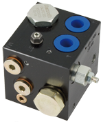
Compact Directional Valves - Non-compensated and Post-compensated - Inlet elements ED Series

TE06

Description

The inlet elements TE-06-_ _ are employed to connect the external P, T lines to the P, T channels inside the ED elements of the Directional Valve Assembly and to connect to the LS ports of the elements equipped with LS channels An LS controlled 3-way compensator provides pressure compensated flow to the ED elements of the Directional Valve Assembly. The same 3-way compensator is also controlled by a pilot relief cartridge and unloads to tank any excess flow in order to limit the primary pressure in the system. In the inlet elements version TE-06-_ _-01, the 3 way compensator can be mechanically blocked and the relief cartridge only controls the LS line pressure. The TE-06-_ _ inlet elements are available with body made of Black Anodized Aluminium (Al). Port sizes can be G 3/8, G 1/2, with test point PM and LS port G 1/4.

General
Label Needed:
  • 1.15 kg (2.53 lbs) TE-06-02-_ _-
  • 1.42 kg (3.13 lbs) TE-06-03-_ _-
Fluid Temperature:
  • –20....+50 (-4....+122) (NBR seals)
Hydraulic
Maximum pressure:
  • 250 bar (3625 psi)
Maximum inlet fl ow:
  • 40 l/min (10.6 gpm) TE-06-02-_ _ version
Maximum inlet fl ow:
  • 90 l/min (23.8 gpm) TE-06-03-_ _ version
Max. rated flow at P1:
  • 40 l/min (10.57 gpm)*
Max. flow through LS drain:
  • 0.7 l/min (0.185 gpm)
Hydraulic fluid General properties: it must have physical lubricating and chemical properties suitable for use in hydraulic systems such as, for example:
  • Mineral oil based hydraulic fluids HL (DIN 51524 part 1). Mineral oil based hydraulic fluids HLP (DIN 51524 part 2). For use of environmentally acceptable fluids (vegetable or polyglycol base) please consult us.
Fluid Temperature:
  • –20....+80 °C (-4....+176 °F) (NBR)
Permissible degree of fluid contamination:
  • ISO 4572: βx≥75 X=10...12 ISO 4406: class 19/17/14 NAS 1638: class 8
Viscosity range:
  • Note: 1) The max. rated flow depends from the directional control element.
  • Note: For applications with different specifications consult us
  • 5....420 mm2/s
RE18300-06-order
RE18300-06-sym
RE18300-06-Pressure-drop
Model
Curve no.
TE-06-02-_ _
1
TE-06-03-_ _
2
RE18300-06-dim
1
Flange specifications for coupling to the ED Directional Valve Elements.
2
For tie rod and tightening torque information see data sheet RE 18301-90.
3
Hydraulic Ports P-T G 3/8, for Inlet Elements TE-06-02…
4
Test Point ports PM and LS port G 1/4.
5
Hydraulic Ports P and T G 1/2, for Inlet Elements TE-06-03…
6
Overall dimensions, including compensator, for TE-06-02-__-01
7
Overall dimensions, including compensator, for TE-06-03-__-01
8
Pressure relief cartridge VS-5-C.