Compact Directional Valves - Non-compensated and Post-compensated - Inlet elements ED Series

TE07

Description

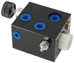
The inlet elements TE-07-__ are employed to connect the external P, T lines to the P, T channels inside the ED elements of the Directional Valve Assembly and to connect to the LS ports of the elements equipped with LS channels. The main functions are: to provide LS controlled pressure compensated flow to the Directional Valve Elements, to limit the primary pressure in the P channels and to unload to Tank the inlet flow when all hydraulic operations must be inhibited, by de-energizing the VEI solenoid operated cartridge. They are available in two versions: TE-07-01-03-… suitable for fixed displacement pumps, and TE-07-02-03-… for variable displacement pumps. The TE-07-__ inlet elements are manufactured with body made of Black Anodized Aluminium (AL). Port sizes are G 1/2, with LS and M test points G1/4. NOTE: the mechanical locking of the 3-way pressure compensator can be supplied upon request.

General
Label Needed:
  • 1.80 kg (3.98 lbs) TE-07-_ _-
Fluid Temperature:
  • –20….+50 (-4….+122) (NBR seals)
Hydraulic
Maximum pressure:
  • 250 bar (3625 psi)
Maximum inlet flow:
  • 90 l/min (23.8 gpm)
Rated flow at P1:
  • 0-30 l/min (0-7.9 gpm)
Hydraulic fluid General properties: it must have physical lubricating and chemical properties suitable for use in hydraulic systems such as, for example:
  • Mineral oil based hydraulic fluids HL (DIN 51524 part 1). Mineral oil based hydraulic fluids HLP (DIN 51524 part 2). For use of environmentally acceptable fluids (vegetable or polyglycol base) please consult us.
Fluid Temperature:
  • –20….+80 °C (-4….+176 °F) (NBR)
Permissible degree of fluid contamination:
  • ISO 4572: βx≥75 X=10...12 ISO 4406: class 19/17/14 NAS 1638: class 8
Viscosity range:
  • Note: For applications with different specifications consult us
  • 5….420 mm2/s
RE18300-07-order
RE18300-07-sym
RE18300-07-Pressure-drop
RE18300-07-dim
1
Flange specifications for coupling to the ED Directional Valve Elements.
2
For tie rod and tightening torque information see data sheet RE 18301-90.
3
Flow restrictor with hand-knob adjustment.
4
Flow restrictor with screw type adjustment.
5
Plug G 1/4 for version TE-07-01-03-…
6
Pressure relief cartridge VS-5-C.
7
Cavity for Solenoid Cartridge, VEI type.
8
Hydraulic Ports P-T G 1/2.
9
G 1/4 ports for pressure gauge connection and LS signal.
10
Overall dimension, including compensator, for TE-07-__-03- -__-01.