Compact Directional Valves - Non-compensated and Post-compensated - Inlet elements ED Series

TE10

Description

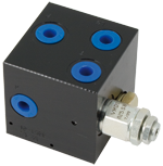
The inlet elements TE-10-__ are employed to connect the external P, T lines to the P, T channels inside the ED elements of the Directional Valve Assembly and to connect to the LS ports of the ED elements equipped with LS channels. The LS signal is sent downstream of the proportional flow restrictor VEP: it provides a proportional pressure compensated flow, across the VEP, for the ED elements of the Directional Valve Assembly, and it unloads the excess flow. The main functions are: to limit the maximum primary pressure in the P line and to supply proportional pressure compensated flow the ED elements of the Directional Valve Assembly. TE-10-__ inlet elements are available with body made of Black Anodized Aluminium (Al). P and T Port sizes can be G 3/8, G 1/2, or SAE 8. Test point M is G 1/4 on BSPP versions, and SAE 4 in SAE versions.

General
Label Needed:
  • 0.83 kg (1.83 lbs) TE-10-02-00-
Label Needed:
  • 0.88 kg (1.94 lbs) TE-10-03-00-
Label Needed:
  • 0.88 kg (1.94 lbs) TE-10-56-00-
Label Needed:
  • 1.08 kg (2.37 lbs) TE-10-02-S_-
Label Needed:
  • 1.16 kg (2.57 lbs) TE-10-03-S_-
Label Needed:
  • 1.16 kg (2.57 lbs) TE-10-56-S_-
Max rated flow at P1:
  • 0-12 l/min (0-3.1 gpm) TE-10-02-00-
  • 0-32 l/min (0-8.4 gpm) TE-10-03-00-
  • 0-32 l/min (0-8.4 gpm) TE-10-56-00-
  • 0-12 l/min (0-3.1 gpm) TE-10-02-S_-
  • 0-32 l/min (0-8.4 gpm) TE-10-03-S_-
  • 0-32 l/min (0-8.4 gpm) TE-10-56-S_-
Fluid Temperature:
  • –20….+50 (-4….+122) (NBR seals)
Hydraulic
Maximum pressure:
  • 210 bar (3045 psi)
Maximum inlet flow:
  • 40 l/min (10.6 gpm)
Rated flow at P1:
  • 32 l/min (8.45 gpm)
Hydraulic fluid General properties: it must have physical lubricating and chemical properties suitable for use in hydraulic systems such as, for example:
  • Mineral oil based hydraulic fluids HL (DIN 51524 part 1). Mineral oil based hydraulic fluids HLP (DIN 51524 part 2). For use of environmentally acceptable fluids (vegetable or polyglycol base) please consult us.
Fluid Temperature:
  • –20….+80 °C (-4….+176 °F) (NBR)
Permissible degree of fluid contamination:
  • ISO 4572: βx≥75 X=10...12 ISO 4406: class 19/17/14 NAS 1638: class 8
Viscosity range:
  • Note: For applications with different specifications consult us
  • 20….380 mm2/s
RE18300-09-order
RE18300-09-sym
RE18300-09-pressure-drop
RE18300-09-dim
1
Flange specifications for coupling to the ED Directional Valve Elements (versions TE-10-02…).
2
For tie rod and tightening torque information see data sheet RE 18301-90.
3
Hydraulic Ports P and T size G 3/8, for versions TE-10-02…
4
Port for pressure gauge connection M size G 1/4, for versions TE-10-02… and TE-10-03…
5
Primary Pressure Relief Cartridge VMD1025 for versions TE-10-02… (refer to RE 18301-91).
6
Flange specifications for coupling to the ED Directional Valve Elements (versions TE-10-03…, and TE-10-56-…).
7
Hydraulic Ports P and T size G 1/2, for versions TE-10-03…
8
Hydraulic Ports P and T size SAE 8, for versions TE-10-56…
9
Port for pressure gauge connection M size SAE 4.
10
Primary Pressure Relief Cartridge VMD1040 for versions TE-10-03…, and TE-10-56-… (refer to RE 18301-91).
11
Proportional Solenoid Cartridge, VEP type, (refer to RE 18301-91).
12
Cavity for Primary Pressure Relief Cartridge VMD1025.
13
Cavity for Primary Pressure Relief Cartridge VMD1040.
14
Cavity for Proportional Solenoid cartridge VEP.