


Δp curves vs. flow in “A-B” free flow direction
GSU
- Compact design and inline mounting for space saving.
- Three sizes provide great adaptability to the system.
- Mounting position is unrestricted.
- Low Δp in the free flow direction.
Description
The “B-A” flow is restricted by a calibrated orifice, while flow “A-B” is always allowed through the incorporated check valve. Pressure compensation is not provided and flow depends from pressure drop and oil viscosity.
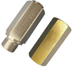
The valve is composed by an hexagonal threaded sleeve with a special inserted cartridge (GSU1): the cartridge is available in different orifice sizes, and can be fitted in either direction (see drawing).
Steel body, zinc plated
General:
Code:
- Pressure P max bar (psi)
GSU 2-14:
- 300 (4300)
GSU 2-38:
- 300 (4300)
GSU 2-12:
- 300 (4300)
GSU 3-14:
- 300 (4300)
GSU 3-38:
- 300 (4300)
GSU 3-12:
- 300 (4300)
The GSU Series valve is a cost effective non-compensated flow control which can be employed in a variety of cases when a one-way restrictor is needed. The smallest sizes can be used also as dampeners for pressure peaks, control of brake engagement.
example 1: GSU2.14.200 = M/F - G 1/4 - hole 2 mm (0.079 inches)
example 2: GSU3.14.075 = F/F - G 1/4 - hole 0.75 mm (0.030 inches)
Ports size / Dimensions
Code
Ports size A-B
L mm (inches)
L1 mm (inches)
L2 mm (inches)
L3 mm (inches)
Hex mm (inches)
GSU 2-14
G 1/4
10 (0.39)
50 (1.96)
/
/
19 (0.75)
GSU 2-38
G 3/8
12 (0.47)
55 (2.17)
/
/
22 (0.87)
GSU 2-12
G 1/2
14 (0.55)
70
/
/
27 (1.06)
GSU 3-14
G 1/4
/
/
13 (0.51)
48 (1.89)
19 (0.75)
GSU 3-38
G 3/8
/
/
13 (0.51)
52 (2.05)
22 (0.87)
GSU 3-12
G 1/2
/
/
14 (0.55)
60 (2.36)
27 (1.06)