SAFETY INFORMATION on our Product Disclaimer Page |
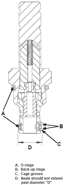
| Provided below are guidelines for installation of HydraForce cartridges, coils, and housings, including tables of torque settings by model number. CARTRIDGE VALVE INSTALLATION STEP 1 Remove the cartridge from packing and inspect to ensure that no external contaminant is present. STEP 2 Inspect all O-rings (A) to ensure there is no damage, such as cuts or nicks. STEP 3 Ensure O-rings and back-up rings (B) are correctly positioned.
NOTE: The O-ring should always be placed toward the higher pressure port or between double back-up rings on bi-directional valves. See page 8.650.1 for seal kit installation.
Check to ensure all back-up rings fit tightly within the O-ring groove.
See illustration. All seals - the O-ring and its two back-up rings - should seat in the cage groove (C) (circled area). If the back-up rings extend out of the cage groove, past diameter (D), push them gently back into position.
INSPECT THE HOUSING STEP 4 Verify correct plumbing of housing by referring to specific product catalog pages for port logic. STEP 5 Inspect cavity for burrs or other machining irregularities which could damage O-rings during installation. If separation from the mounting surface is required, refer to page 8.250.1 for panel mount spacer plates. |
 |
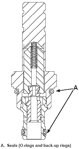
| STEP 6 Before installing the cartridge, lubricate all seals (O-rings and back-up rings) with the same oil that is used in the application. To lubricate the seals (A), lightly apply a small amount of oil on them. This thin coat of oil will allow the cartridge and seals to slide more easily into the cavity.
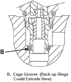
If the seals are too dry, the back-up rings could dislodge from the cage groove (B) and cause seal damage. The diagram shows the location of the cage groove and where the back-up rings could extrude.
|
 |
 |
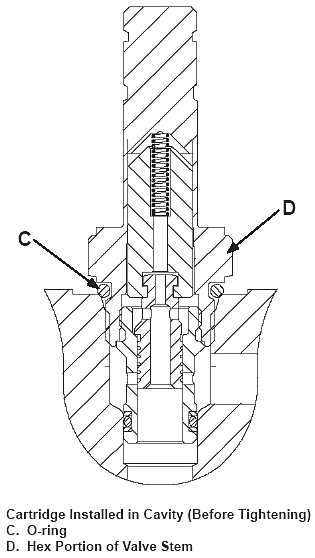
| STEP 7 It is important to install the cartridge valve into the cavity correctly. Insert the cartridge into the cavity and tighten by hand in a clockwise manner. You should be able to screw the valve in with little resistance up to the O-ring (C) below the hex portion of the valve stem (D). See illustration.
|
 |
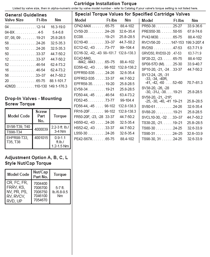
| STEP 8 Continue to screw in the cartridge with a torque wrench and tighten to the specified torque. See the Cartridge Installation Torque Table below. if your valve is not listed, refer to the dimensional drawing on the Catalog page for the specific valve model.
It is important to use the specified torque for each valve to ensure the optimal performance of the cartridge.
If the valve is tightened above the specified torque value, it may cause the spool or poppet to stick.This occurs because overtightening the cartridge can deform or damage internal components.
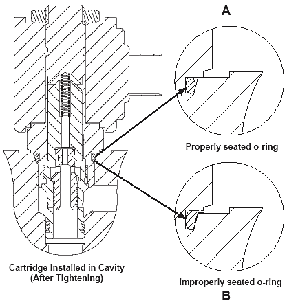
Before installing the coil, inspect the cartridge to ensure the O-ring is properly seated (A). |
 |
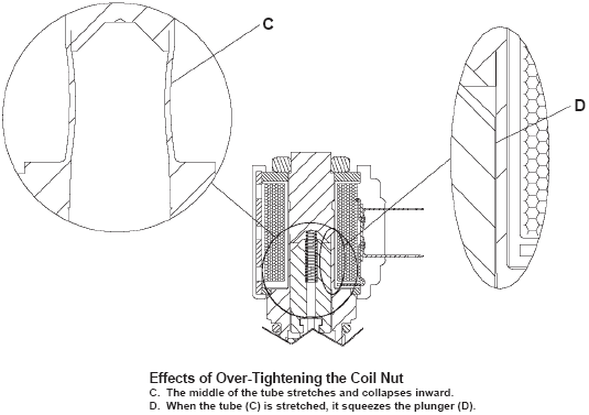
| COIL INSTALLATION It is important to use the specified torque when tightening the coil nuts. For example, if the nut is tightened above the specification on the 08, 60, 68, 80 size 2 position actuators, the stainless steel tube may stretch. The stretching causes the inside of the tube around the plunger to collapse (C), which may cause the plunger to stick (D) in the energized or de-energized position. This is shown in the diagram below.
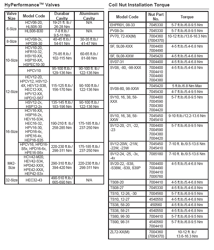
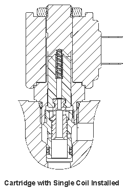
NOTE: If installing two coils see Step 9A. NOTE: If installing a coil on a PV7x or ZL7x series valve, see Step 9B. STEP 9 If the valve uses a single coil, slide the coil over the valve stem. Tighten the coil nut to the specified torque. See the specifications in the Coil Nut Installation Torque Table below.
If the valve requires two coils, install them separately. follow Step 9A.
STEP 9A (Two-Coil Valves Only) Slide the first coil over the valve stem. Place the washer on top of the first coil, then install the second coil.
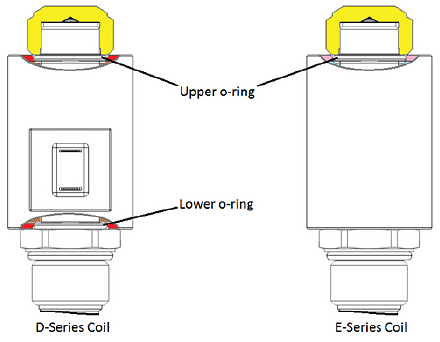
STEP 9B (PV7x and ZL7x Valves Only) For D-series coils, install both the upper and lower o‑rings.
For E-series coils, install the upper o-ring only. NOTE: Do not operate or pressurize PV7x or ZL7x series valves without the installation of the coil retaining nut. To assure proper function, the coil nut must be installed to retain the coil. STEP 10
Finally, install and tighten the coil nut to the specified torque.
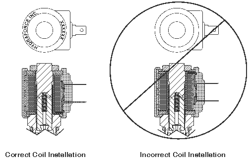
NOTE: It is important to install coils correctly to ensure they operate as designed. If a coil is installed upside down, the magnetic flux path will be weak and wil not be able to shift the spool or poppet. See diagram showing correct and incorrect coil installation To ensure the coil is right side up, verify that the HydraForce imprint on the coil is facing upward.
|
 |
 |
 |
 |
