
Efficient Solutions for Trailed Equipment

Feeding the world today takes more than a green thumb, it takes technology: smart and efficient equipment that helps farmers squeeze every dollar out of a crop. The value agricultural OEMs provide lets farmers maximize resources, reclaim their time, and get more done, sun to sun.
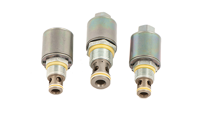
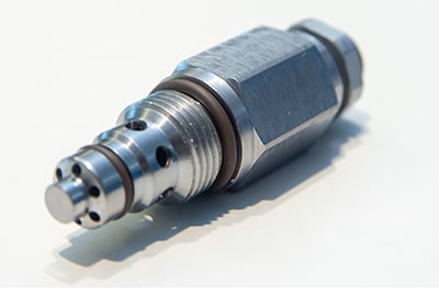
HydraForce helps you provide the most advanced and reliable technology to the market. Fluid power is the workhorse of modern agricultural machinery, and compact efficient cartridge valves from HydraForce allow designers the most flexibility in crafting systems that deliver precise metered power to implements, drive systems, and actuators. Reliable and serviceable cartridge valve technology makes complex distributed on-board control systems possible for trailed equipment, achieving precision that would not otherwise be possible relying on tractor hydraulics.
At HydraForce our talented sales and application engineering staff offer you the expertise and creativity to build solutions that let your products stand out in the crowded marketplace. We help you accelerate your time to market, and add real value for your customers.
Application Details
Powertrain
Transmission and PTO Solutions
- Clutch engage / disengage, Power Shift
- Accurate clutch pressure control
- Lubrication pressure control
- Main system pressure regulation
- Diff. Lock engage / disengage
- PTO control
(image)
The circuit shown has a nominal flow rate of 114 lpm/30 gpm with a main system relief valve.
- Drop-In Valves Proportional Pressure Control Optimizes Clutch
Engagement and Lube Oil Cooler Performance - Modulating Valve Concept - For Soft and Modulated Engagement of
Mechanical Operated Clutches
(image)
CLUTCH ENGAGEMENT PERFORMANCE (TS98-T34)
image x 2
Optimize tractor powertrain systems with hydraulic cartridge valves and manifolds with programmable controllers.
(image)
Variable Speed Fan Drives
Fan Drive Solutions
• Flow rates up to 190 lpm (50 gpm)
• Fail safe high or low
• Preconfigured controls available
• Reduce horsepower consumption by up to 30%
(image)
Control valves with multiple temperature inputs can be used to provide variable fan speed control depending on air temperature, load, and cooling requirements. If the radiator gets clogged, two-position, four-way solenoid valves can automatically reverse fan direction.
Electronic control of the hydraulic cooling system can be achieved using either an EFDR1 programmable valve driver or a CoreTek™ controller (ECU).
(image)
Suspension Systems
How it works:
Hydro-pneumatic Suspension Diagram In a hydro-pneumatic suspension system, a cylinder and accumulator replace the torsion or leaf spring. The accumulator acts as the spring and, with restrictions for oil flow, damping can be accomplished.
(image)
Basic Suspension Solution
This basic hydro-pneumatic suspension system is idea for cabin or seat suspension or for tractors with a small axle load range.
• Single or double acting cylinder
• Accumulator
• Level control manifold
• Cartridge valves • Pressure ratio 1:3 between empty and max
loaded axle
Advanced Suspension Solution
• Double-acting system
• Independent accumulators for cylinder piston and rod side
• Constant or variable pressure on rod side
• Integral sensors
• Software developement
• Pressure ratio of more than 1:20 between empty and max
loaded axle
(IMAGE)
Suspension Options — Damping and Lockout
LOCKOUT —
Sometimes it is desirable to lock out the suspension. This can be accomplished with a lock-out manifold that can be used to over-damp the suspension or completely lock the connection between the hydraulic cylinder and accumulator.
(IMAGE)
DAMPING —
With an intelligent control algorithm in combination with a proportional valve which acts as a variable orifice to restrict oil flow between the cylinder and accumulator, a semi-active suspension system can be created.
(IMAGE)
(MACHINE IMAGE)
Primary Function
Dual Accumulator Charging
Primary Steering and Brake Solution
• Dynamic Accumulator Charging Circuits
used in conjunction with steering and
braking units
— Primary Flow to the brake section of
the circuit
— Auxiliary Flow diverted to the directional
function
(image)
RVD50-20P — PED rated product for accumulator charging circuits
The RVD50-20P is a direct-acting, poppet type, hydraulic safety relief valve. The RVD50-20P is suitable for use as a safety accessory in Category IV, Group 2 applications according to the pressure equipment directive (PED) 97/23/EC, which is primarily concerned with the protection of Accumulator Circuits. This is particularly well suited for dynamic brake charging circuits where pressure clipping and quick discharge of energy is often needed.
(image)
(machine image)
Auxiliary Function
Hydraulic Power Take-Off with Flow Sharing
HydraForce Auxiliary Function Circuits provide precise control of flows for balers, crop harvesters, and other auxiliary equipment.
Higher productivity requires higher flows, and HydraForce cartridge valves can handle flows up to 300 lpm (79 gpm).
When the flow demand exceeds the system supply, flow sharing can help maintain effective control.
(image)
(image)
Hitch Control
Front and Rear Hitch Control Circuit
(image)
Hitch (Lift Control)
As tractor power and sophistication increases, so do the flow rates. HydraForce SPCL16-30 valves gives precise control up to 150 lpm (40 gpm) while holding the loads with extremely low leakage. HydraForce RV10-28 and RVD50-20 relief valves limit the shock pressure peaks whilst having very low leakage and hysteresis.
- Gives precise control up to
150 lpm (40 gpm) - Limit shock pressure peaks
- Low leakage and hysteresis
Proportional Hitch Control Circuit
(image)
Rear Hitch Control Circuit
(image)
HITCH RELEASE AND POWER LIFT CIRCUIT
Positioning and attaching the rear lift hitch attachment from the cab gives increased productivity and improved operator comfort and safety.
(image)
(image)
Electronic Controls
HydraForce is pleased to offer a full line of electronic vehicle control products integrating engine, transmission and other machine functions into a common J1939 or CAN Open Data Link control circuit.
These systems consist of rugged, field-proven components suitable for heavy-duty operating conditions. PWM digital signal logic maximizes efficiency, response and signal integrity under harsh environmental conditions. Reliability has been proven through extensive testing, as well as years of real-world application experience.
This is a complete line of the most rugged, heavy duty vehicle machine controllers, monitors, displays and electrical connectors for motion control and integrated machine control applications in mobile, off-highway and material handling equipment.
- Reliable operation in the most demanding mobile equipment applications
- Operating temperatures from -40 to 85°C
- Chemical splash immunity
- Moisture resistance to IP67 specifications
- Fully resistant to EMI/RFI
- Vibration resistant to 8 Grms (random) 24–200 Hz, 3-axis