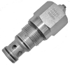
Cartridge Valves - Directional Control Valves - Logic elements

VLSR-16A

RE18321-74-01(2023-11-07)
Description

When pressure at 1 rises above the selected spring bias pressure against the spool, the valve shifts to allow block flow from 2 to 1. The differential pressure between 1 and 3, across an internal orifice, is additive to the spring bias pressure. Note that flow, restricted by the internal orifice, can be transmitted from 3 to 1 and 2. The valve may be used in switching or compensation type applications.

¹) Measured at 200 bar (2900 psi)

²) Standard version X=00 type

³) Only external seals for 10 valves

General:
Max. operating pressure:
  • 350 bar (5000 psi)
Max. Flow:
  • 120 l/min (32 gpm)
Max. internal leakage¹):
  • 200 cm³/min. (12 cu.in./min.)
Fluid temperature range:
  • -30 to 100 °C (-22 to 212 °F)
Installation torque:
  • 108 - 122 Nm (80 - 90 ft-lbs)
Weight²):
  • 0.5 kg (1.1 lbs)
Standard internal orifice:
  • 0.6 mm
Cavity:
  • CA-16A-3C (see data sheet 18325-70)
Lines bodies and standard assemblies:
  • Please refer to section “Hydraulic integrated circuit” or consult factory
Seal kit³):
  • Code: RG16A9010520100
  • material no: R901111388
Fluids:
  • Mineral-based or synthetics with lubricating properties at viscosities of 10 to 500 mm²/s (cSt)
Recommended degree of fluid contamination:
  • Nominal value max. 10µm (NAS 8) / ISO 4406 19/17/14
Installation position:
  • No restrictions
Other Technical Data:
  • See data sheet 18350-50
RE18321-74-02(2023-11-07)

Note: Special settings available. Contact factory authorized representative for ordering code.

RE18321-74-order(2023-11-07)
RE18321-74-dim(2023-11-07)