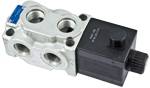
- 6 way 2 position valve.
- Directional spool valve with direct solenoid control.
- Hydraulic / pneumatic pilot , or manual push and twist control available as option.
- Control spool operated by solenoid, with easily removable coil fastened by a ring nut.
- Wet pin tube for DC coil, with push rod for mechanical override in case of voltage shortage.
- Unrestricted 360° orientation of DC coil.
- Control spool held in normal position by return spring.
- Optional manual override (push-button or screw type).
- Connectors available: DIN 43650 – ISO 4400, AMP Junior, DT04-2P (Deutsch), Free leads.
- Size 10
- Series 00
- Maximum operating pressure 310 bar (4500 psi)
- Maximum flow 140 l/min (36.98 gpm)
- Ports G 1/2 - G 3/4 - SAE12
VS311-VS312-VS315
A valve basically consists of a housing (1), a control spool (2), a return spring (3) and a solenoid (5). It is designed to connect two inlet lines P1 – P2 (normally a set of hoses) and divert them to either the outlet ports (C1 – C4) with spool in position “0”, when the solenoid is de-energized, or to the outlet ports (C2 – C3) with spool in position “1”, when the solenoid is energized.
With the coil de-energized, the return spring (3) pushes back the spool (2) and holds it in position “0”.
The coil (5) is fastened to the tube by the ring nut (6).
The manual override (6) allows to shift the spool (2) also in case of voltage shortage.
An external drain, to be connected to tank, ensures shifting operations also at higher working pressure.
Hydraulic / pneumatic pilot control for spool shifting is available upon request.
![]() For applications with different specifications consult us
For applications with different specifications consult us
Code
Voltage [V]
Connector type
Coil description
Marking
Coil Mat no.
OB 01
12 DC
EN 175301-803(Ex. DIN 43650)
C6501 12DC
12 DC
R933000100
OB 03
12 DC
AMP JUNIOR
C6503 12DC
12 DC
R933000119
OB 07
12 DC
DEUTSCH DT 04-2P
C6507 12DC
12 DC
R933000107
OB 31
12 DC
Cable 350 mm long
C6531 12DC
12 DC
R933000104
AD 01
13 DC
EN 175301-803(Ex. DIN 43650)
C6501 13DC
13 DC
R933000101
AD 07
13 DC
DEUTSCH DT 04-2P
C6507 13DC
13 DC
R933000112
OC 01
24 DC
EN 175301-803(Ex. DIN 43650)
C6501 24DC
24 DC
R933000102
OC 03
24 DC
AMP JUNIOR
C6503 24DC
24 DC
R933000120
OC 07
24 DC
DEUTSCH DT 04-2P
C6507 24DC
24 DC
R933000111
OC 31
24 DC
Cable 350 mm long
C6531 24DC
24 DC
R933000110
AC 01
27 DC
EN 175301-803(Ex. DIN 43650)
C6501 27DC
27 DC
R933000103
AC 03
27 DC
AMP JUNIOR
C6503 27DC
27 DC
R93307055
AC 07
27 DC
DEUTSCH DT 04-2P
C6507 27DC
27 DC
R933000113
OD 01
48 DC
EN 175301-803(Ex. DIN 43650)
C6501 48DC
48 DC
R933000114
General:
Valve weight:
- 5.1 kg (11.2 lbs)
Mounting position:
- unrestricted
Fluid Temperature:
- –20....+50 (-4....+122) (NBR seals)
Hydraulic:
Maximum pressure with external drain (“E” type):
- 310 bar (4500 psi)
Maximum pressure with internal drain (“I” type):
- 250 bar (3625 psi)
Maximum pressure with internal drain and 6F or 6G scheme:
- 310 bar (4500 psi)
Maximum flow:
- 140 l/min (36.98 gpm)
Pilot pressure needed for hydraulic / pneumatic control:
- max 200 bar (2900 psi) - min 4 (58) with external drain. For versions with internal drain, the pilot pressure required should be at least 11 times higher than inlet pressure (ratio 11:1).
Hydraulic fluidGeneral properties: it must have physical lubricating and
chemical properties suitable for use in hydraulic systems such as, for
example:
- Mineral oil based hydraulic fluids HL (DIN 51524 part 1). For use of environmentally acceptable fluids (vegetable or polyglycol base) please consult us.
Fluid Temperature:
- –20....+80 °C (-4....+176 °F) (NBR seals)
Permissible degree of fluid contamination:
- ISO 4572: βx ≥ 75 X = 12...15 NAS 1638: class 9
Viscosity range:
- 5....420 mm²/s
Internal leakage with 100 bar (1450 psi) secondary pressure at C:
- min. 15 cc/min (0.9 in³/min) - max. 40 (2.4)
Electrical:
Voltage type:
- DC
Voltage tolerance (nominal voltage):
- -10 .... +10 %
Duty:
- Continuous, with ambient temperature ≤ 50°C (122°F)
Coil wire temperature not to be exceeded:
- 150 °C (302 °F)
Insulation class:
- H
Compliance with:
- Low Voltage Directive LVD 73/23/EC (2006/95/EC), 2004/108/EC
Coil weight with DIN 43650 – ISO 4400 connector:
- 1.05 kg (2.3 lbs)
Voltage:
- 12 V 13 V 24 V 27 V 48 V
Voltage type:
- DC DC DC DC DC
Power consumption:
- 44 W 44 W 44 W 44 W 44 W
Current (nominal at 20 °C (68 °F)):
- 3.6 A 3.4 A 1.8 A 1.6 A 0.9 A
Resistance (nominal at 20 °C (68 °F)):
- 3.2 Ω 3.6 Ω 12.8 Ω 16.9 Ω 50.5 Ω
Model
Curve no.
P1>C1
P1>C2
P2>C4
P2>C3
VS311
2
2
2
2
VS312-VS315
1
1
1
1
Measured with hydraulic fluid ISO-VG32 at 45° ±5 °C (113° ±9 °F); ambient temperature 20 °C (68 °F).
Model
Curve no.
VS311
1
VS312-VS315
2
Flow across both ways: forward across P1>C1 and reverse across C4>P2
1
Ports P1, P2, C1, C2, C3, C4.
2
The mounting surface fatness must comply with specifications.
3
Two through holes reccomended screws M8×45 with strength class DIN 8.8.Torque 15 – 16 Nm (11.1–11.8 ft-lb).
4
Ring nut for coil locking Ø 34 mm (1.34 inch).Torque 7–8 Nm (5.2 – 5.9 ft-lb ).
5
Solenoid tube Ø 25,4 mm (1.00 inch).
6
Minimum clearance needed for connector removal.
7
External drain plug available with G 1/4 and SAE 4 port.
8
Identification label.
9
Optional push-button, 4P type, manual override for spool opening: it is pressure stuck to the ring nut for coil locking.Mat no. R933003424
10
Optional screw type manual override, 4F or 4X types, for spool opening: it is screwed (torque 8-9 Nm (5.9-6.6 ft-lb)) to the tube as replacement of the coil ring nut. Mat no. R933003713 zinc plated, Mat no. R933009577 stainless steel.
11
Dimensions of manual version, push and twist type.
12
Dimensions of hydraulic / pneumatic piloted version. Pilot port plug available with G 1/4.