Compact Directional Valves - Diverters - 3-ways

VS81-VS82-VS84-VS85

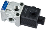
3 way 2 position valve.

Directional spool valve with direct solenoid control.

Hydraulic / pneumatic pilot, or manual push and twist control available as option.

Control spool operated by solenoid, with easily removable coil fastened by a ring nut.

Wet pin tube for DC coil, with push rod for mechanical override in case of voltage shortage.

Unrestricted 360° orientation of DC coil.

Control spool held in normal position by return spring. Optional manual override (push-button or screw type). Connectors available: DIN 43650 – ISO 4400, AMP Junior, DT04-2P (Deutsch), Free leads.

Size 6

Series 00

Maximum operating pressure 310 bar (4500 psi)

Maximum flow 60 l/min (15.85 gpm)

Ports G 3/8 - G 1/2 - SAE8

NEW spool position sensor available for this valve. See RE18300-30

RE18302-02-Order
RE18302-02-sym
RE18302-02-01

A valve basically consists of a housing (1), a control spool (2), a return spring (3) and a solenoid (5). It is designed to select which one of two circuits (C1 or C2) is to be supplied with the oil delivered from one single hose (P): with spool in position “0”, when the solenoid is de-energized, the flow goes from P to C1, with spool in position “1”, when the solenoid is energized the flow goes from P to C2.

With the coil de-energized, the return spring (3) pushes back the spool (2) and holds it in position “0”.

The coil (5) is fastened to the tube by the ring nut (6).

The manual override (7) allows to shift the spool (2) also in case of voltage shortage.

An external drain, to be connected to tank, ensures shifting operations also at higher working pressure.

Hydraulic / pneumatic pilot control, or manual push and twist control for spool shifting are available upon request

 
Voltage [V]
Connector type
Coil description
Marking
Coil Mat no.
OB 01
12 DC
EN 175301-803(Ex. DIN 43650)
C4801 12DC
12 DC
R933000063
OB 03
12 DC
AMP JUNIOR
C4803 12DC
12 DC
R933000065
OB 07
12 DC
DEUTSCH DT 04-2P
C4807 12DC
12 DC
R933000068
OB 31
12 DC
Cable 350 mm long
C4831 12DC
12 DC
R933000064
AD 01
13 DC
EN 175301-803(Ex. DIN 43650)
C4801 13DC
13 DC
R933000069
AD 07
13 DC
DEUTSCH DT 04-2P
C4807 13DC
13 DC
R933000073
OC 01
24 DC
EN 175301-803(Ex. DIN 43650)
C4801 24DC
24 DC
R933000076
OC 03
24 DC
AMP JUNIOR
C4803 24DC
24 DC
R933000071
OC 07
24 DC
DEUTSCH DT 04-2P
C4807 24DC
24 DC
R933000075
OC 31
24 DC
Cable 350 mm long
C4831 24DC
24 DC
R933000070
AC 01
27 DC
EN 175301-803 (Ex. DIN 43650)
C4801 27DC
27 DC
R933000077
AC 07
27 DC
DEUTSCH DT 04-2P
C4807 27DC
27 DC
R933000074
OD 01
48 DC
EN 175301-803(Ex. DIN 43650)
C4801 48DC
48 DC
R933000078
General:
Valve weight:
  • 2.06 kg (4.54 lbs)
Fluid Temperature:
  • –20....+50 (-4....+122) (NBR seals)
MTTFd:
  • 150 years see RE 18350-51
Hydraulic:
Maximum pressure with external drain (“E” type):
  • 310 bar (4500 psi)
Maximum pressure with internal drain (“I” type):
  • 250 bar (3625 psi)
Maximum flow:
  • 60 l/min (15.85 gpm)
Hydraulic fluidGeneral properties: it must have physical lubricating and chemical properties suitable for use in hydraulic systems such as, for example:
  • Mineral oil based hydraulic fluids HL (DIN 51524 part 1). For use of environmentally acceptable fluids (vegetable or polyglycol base) please consult us.
Fluid Temperature:
  • –20....+80 °C (-4....+176 °F) (NBR seals)
Permissible degree of fluid contamination:
  • ISO 4572: βₓ ≥ 75 X = 12...15 NAS 1638: class 9
Viscosity range:
  • 5....420 m m²/s
Internal leakage with 100 bar (1450 psi) secondary pressure at C:
  • min.10 cc/min (0.61 in³/min)
  • max. 20 cc/min (1.2 in³/min)
Electrical:
Voltage type:
  • DC
Voltage tolerance (nominal voltage):
  • -10 +10%
Duty:
  • Continuous, with ambient temperature ≤ 50°C (122°F)
Coil wire temperature not to be exceeded:
  • 150°C (302°F)
Insulation class:
  • H
Compliance with:
  • Low Voltage Directive LVD 73/23/EC (2006/95/EC), 2004/108/EC
Coil weight with DIN 43650 – ISO 4400 connector:
  • 0.215 kg (0.44 lbs)
Voltage:
  • 12 V
  • 13 V
  • 24 V
  • 27 V
  • 48 V
Voltage type:
  • DC
  • DC
  • DC
  • DC
  • DC
Power consumption:
  • 36 W
  • 36 W
  • 36 W
  • 36 W
  • 36 W
Current (nominal at 20 °C (68 °F)):
  • 3.0 A
  • 2.77 A
  • 1.53 A
  • 1.32 A
  • 0.75 A
Resistance (nominal at 20 °C (68 °F)):
  • Note: For applications with different specifications consult us
  • 3.97 Ω
  • 4.68 Ω
  • 15.67 Ω
  • 20.42 Ω
  • 63.60 Ω
RE18302-02-02
Model
Curve no.
VS 81
1
VS 82/85
2

Measured with hydraulic fluid ISO-VG32 at 45° ±5 °C (113° ±9 °F); ambient temperature 20 °C (68 °F).

RE18302-02-03
Drain type
Curve No.
External (-E-)
1
Internal (-I-)
2
RE18302-02-dim
1
Solenoid tube Ø 19 mm (0.75 inch).
2
Plug for version with external drain.
3
Ring nut for coil locking Ø 26.5 mm (1.04 inch).
Torque 5-6Nm (3.6-4.4 ft-lb ).
4
Two through holes for installation.
Recommended screws M6 with strength class DIN 8.8.
Torque 9-10 Nm (6.6-7.4 ft-lb).
5
Ports P, C1, C2: G 3/8, G 1/2, SAE 8.
6
External drain and hydraulic, or pneumatic pilot port G 1/4, SAE 4.
7
Optional push-button type manual override for spool opening: it is pressure stuck to the ring nut for coil locking.
Mat no. R933000043.
8
Optional screw type manual override for spool opening: it is screwed (torque 6-7Nm (4.4-5.2 ft-lb)) to the tube as replacement of the coil ring nut. Mat no. R933007215.
9
Dimensions of optional manual version, push and twist type.
10
Plug for version with internal drain.
11
Minimum clearance needed for connector removal.
12
Identification label.
13
Hydraulic, or pneumatic pilot connector.
RE18302-02-04