Compact Directional Valves - Non-compensated and Post-compensated - Directional elements ED Series

ED-IP

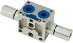
Valve element 4 ways, 3 positions.

Hydraulically direct operated spool.

Hydraulic operating element bolted on.

Hydraulic operating element available with inlet port: G1/4 DIN 3852; 9/16-18 UNF 2-B.

The control spool is held in the central position by return springs.

Size 6

Series 00

Maximum operating pressure 310 bar (4500 psi)

Maximum flow 45 l/min (11.9v gpm)

Port connections G 3/8 - G 1/2 - SAE6 - SAE8

RE18301-07-order

Symbols

RE18301-07-sym

Spool variants

RE18301-07-spool

In neutal position, the valves cross section are as follows:

E_I ≥ 20% of nominal cross section.

E_S ≥ 2% of nominal cross section.

RE18301-07-functional

The sandwich plate design directional valve elements L8_ P5... are compact direct hydraulic operated valves which control the start, the stop and the direction of the oil flow. These elements basically consist of a stackable housing (1) with a control spool (2), two hydraulic operating blocks (5), and two return springs (4).

The hydraulic pressure in one of the blocks (5) pushes the control spool (2) from its neutral-central position “0” to the required end position “a” or “b”, and the required flow from P to A (with B to T), or P to B (with A to T) is achieved. When pressure is removed from either one of blocks (5), the return spring (4) pushes the spool thrust washer (3) back against the housing and the spool returns in its neutral-central position “0”.

General
Valve element with 2 hydraulic controls:
  • 1.23 kg (2.71 lbs)
Fluid Temperature:
  • -20....+50 (-4....+122) (NBR seals)
Hydraulic

For applications with different specifications consult us

Maximum pressure at P, A and B ports:
  • 310 bar (4500 psi)
Maximum pressure at T to prevent damages:
  • 100 bar (1450 psi)
Reccomended maximum pressure at T during operation:
  • 10 bar (145 psi)
Max. pilot pressure:
  • 35 bar (508 psi)
Min. pilot pressure:
  • bar (psi) refer to page 4
Maximum inlet flow:
  • 45 l/min (11.9 gpm)
Hydraulic fluidGeneral properties: it must have physical lubricating and chemical properties suitable for use in hydraulic systems such as, for example:
  • Mineral oil based hydraulic fluids HL (DIN 51524 part 1). For use of environmentally acceptable fluids (vegetable or polyglycol base) please consult us.
Fluid Temperature:
  • -20....+80 °C (-4....+176°F) (NBR seals)
Permissible degree of fluid contamination:
  • ISO 4572: βₓ≥75 X=10...12
  • ISO 4406: class 19/17/14
  • NAS 1638: class 8
Viscosity range:
  • 20....380 mm²/s (optimal 30....46)

Ordering code S2: 10 l/min (2.64 gpm).

RE18301-07-order-code1

Ordering code S4: 20 l/min (5.28 gpm).

RE18301-07-order-code2

Ordering code S6: 30 l/min (7.92 gpm).

RE18301-07-order-code3

The performance curves are measured with flow going across and coming back, like P>A and B>T, with symmetrical flow areas and with back-pressure in T ≤ 10 bar (145 psi).

RE18301-07-ext-dim
1
Hydraulic operating element available with inlet port: G1/4 DIN 3852; 9/16-18 UNF 2-B (SAE 6).
2
Flange specifications for coupling to ED intermediate elements with ports G 3/8 and SAE 6.
3
Flange specifications for coupling to ED intermediate elements with LS channels and with ports G 3/8 and SAE 6.
4
Flange specifications for coupling to ED intermediate elements with ports G 1/2 and SAE 8.
5
Flange specifications for coupling to ED intermediate elements with LS channels with and ports G 3/8 and SAE 6.
6
For tie rod and tightening torque information see data sheet RE 18301-90.
7
Four threaded holes M5 for fitting a secondary flangeable element (only for elements with ports G 3/8 and SAE 6).For screws and tightening torques see data sheet RE 18301-90.
8
A and B ports.
9
O-Rings for P and T ports.
10
Identification label.