Compact Directional Valves - Non-compensated and Post-compensated - Directional elements ED Series

ED4-PTC1

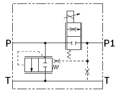
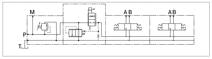
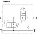
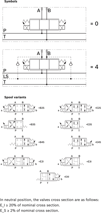
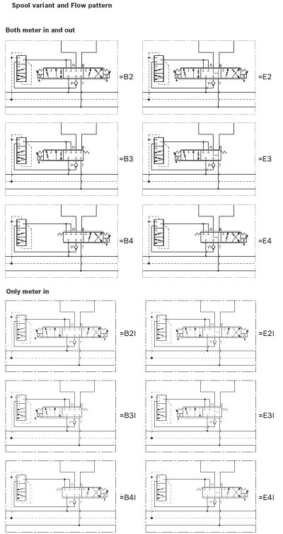
Valve element with direct proportional pressure compensated control of inlet, P line, flow.

Three way pressure compensator included.

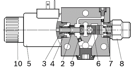
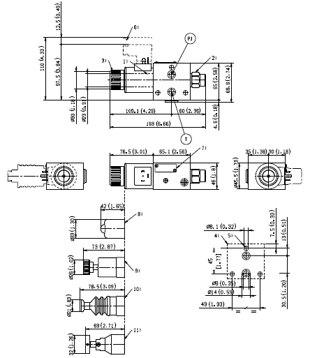
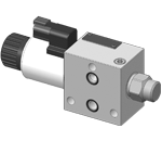
Wet pin proportional tube for removable DC coil.

In the de-energized condition, the control spool is held in normal position by return spring.

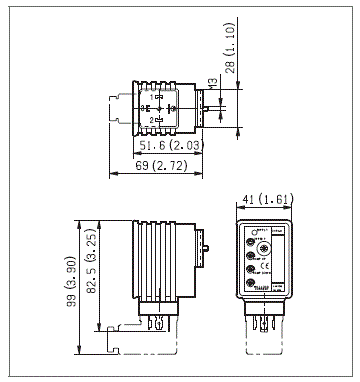
Solenoid tube with push rod for mechanical override; nickel plated surface.

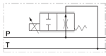
Manual override (push-button, screw type) available as option.

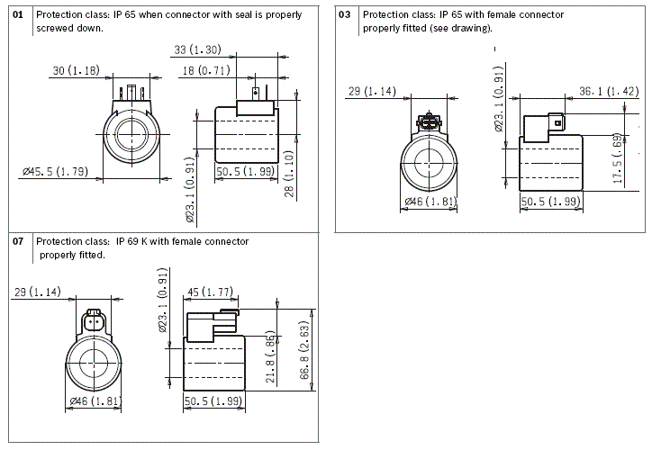
Plug-in connectors available: EN 175301-803 (Was DIN 43650); DT04-2P (Deutsch); Amp Junior.

Size 6

Series 00

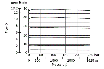
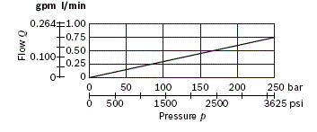
Maximum operating pressure 250 bar (3625 psi)

Maximum flow 40 l/min (10.6 gpm)

NEW spool position sensor available for this valve. See RE18300-30

RE18301-18-order(2023-10-20)
RE18301-18-sym(2023-10-20)
RE18301-18-01(2023-10-20)
RE18301-18-02(2023-10-20)

The sandwich plate design elements L808103C… are 3 way proportional pressure compensated direct solenoid operated valves. They control the inlet (P) flow and allow through (out of P1) only the flow required by the downstream operators; the excess oil, pressurized at working pressure, is diverted from the inlet P line to Tank. The combination of the proportional regulator with the unloading compensator guarantees stable and constant flow, independently from the working pressure. The proportional control is achieved by a wet pin proportional screwed-in tube, with removable coil which is energized by an external electronic feed regulator; the electronic regulator performs an “open loop” control of the current supplied to the coil.

These elements basically consist of a stackable housing (1) with a control spool (2), a solenoid (3), and one return spring (4); additionally there is a compensator (6), with a preset spring (7), a spring retainer plug (8) and a drain orifice (9). A coil (5) is held to the solenoid tube by the ring nut (10).

With the solenoid de-energized, the spool stays in the closed position; the pressure overcomes the compensator spring (7) and the inlet (P) oil is unloaded to Tank at the Δp value shown by the characteristic curve. Pressure at (P1) is drained to Tank through the orifice and drops to zero.

By energizing the solenoid (3) through the electronic feed regulator, the control spool (2) is displaced from its rest position proportionally to the current; the corresponding opening allows a pressure compensated flow to proceed to P1, while the excess flow is diverted to Tank.

With the solenoid (3) de-energized, the return spring (4) pushes the spool (2) to its rest position “0” fully closed. No flow goes to P1 and any residual pressure at P1 is drained through the orifice. The compensator (6) is pushed fully open all the oil is unloaded to Tank.

Code
Voltage [V]
Connector type
Coil description
Marking
Coil Mat no.
=OB 01
12 DC
EN 175301-803 (Ex. DIN 43650)
GP45 01 - 45 K4
12 DC
R901022180
=OB 03
12 DC
AMP JUNIOR
GP45 03 - 45 C4
12 DC
R901022680
=OB 07
12 DC
DEUTSCH DT 04-2P
GP45 07 - 45 K40
12 DC
R901272648
=OC 01
24 DC
EN 175301-803 (Ex. DIN 43650)
GP45 01 - 45 K4
24 DC
R901022174
=OC 03
24 DC
AMP JUNIOR
GP45 03 - 45 C4
24 DC
R901022683
=OC 07
24 DC
DEUTSCH DT 04-2P
GP45 07 - 45 K40
24 DC
R901272647
General
Valve element with 1 solenoid, pins EN175301-803:
  • 1.53 kg (3.37 lbs)
Fluid Temperature:
  • -30....+90 (-22....+194) (NBR seals)
Hydraulic
Maximum pressure at P:
  • 250 bar (3625 psi)
Maximum flow rated at P1:
  • 40 l/min (10.6 gpm)
Maximum inlet flow:
  • 50 l/min (13.2 gpm)
Hydraulic fluidGeneral properties: it must have physical lubricating and chemical properties suitable for use in hydraulic systems such as, for example:
  • Mineral oil based hydraulic fluids HL (DIN 51524 part 1). For use of environmentally acceptable fluids (vegetable or polyglycol base) please consult us.
Fluid Temperature:
  • -30....+100°C (-22....+212°F) (NBR seals)
Permissible degree of fluid contamination:
  • ISO 4572: βₓ≥75 X=12...15 NAS 1638: class 9
Viscosity range:
  • 20....380 (optimal 30.... 46) mm2/s
Electrical
Voltage type:
  • 120 Hz PWM
Voltage tolerance (nominal voltage):
  • -10 .... +10%
Duty:
  • Continuous, with ambient temperature ≤ 90°C (194°F)
Coil wire temperature not to be exceeded:
  • 180 °C (356 °F)
Insulation class:
  • H
Compliance with:
  • Low Voltage Directive LVD 73/23/EC (2006/95/EC), 2004/108/EC
Coil weight:
  • 0.335 kg (0.732 lbs)
Voltage:
  • 12 V
  • 24 V
Nominal 100% current:
  • 1.8 A
  • 1.2 A
Coil resistance (Cold nominal value at 20°C (68°F)):
  • Note: For applications with different specifications consult us
  • 3.3 Ω
  • 7.2 Ω

RE18301-18-03(2023-10-20)
Curve no.
Nominal flow
1
C2 - C4 - C6
2
C8 - C9

RE18301-18-04(2023-10-20)

%A = Percentage of the maximum current supplied to the coil

Curve no.
Nominal flow
1
C2
2
C4
3
C6
4
C8
5
C9

Compensated flow curves

RE18301-18-05(2023-10-20)

Drain to tank

RE18301-18-06(2023-10-20)

RE18301-18-dim1(2023-10-20)
1
Solenoid tube Ø 23 (0.9 inch).
3
Ring nut for coil locking (Ø 30.3 mm (1.18 inch)); torque 6–7 Nm (4.4 – 5.2 ft-lb).
4
Flange specifications for coupling to ED intermediate elements.
5
For tie rod and tightening torque information see data sheet RE 18301-90.
6
Clearance needed for connector removal.
7
Identification label.
8
Optional push-button manual override, 0P type, for spool opening: it is pressure stuck to the ring nut for coil locking.Mat no. R933003424.
9
Optional screw type manual override, 0F type, for spool opening: it is screwed (torque 6-7 (4.4-5.2 ft-lb)) to the tube as replacement of the coil ring nut. Mat no. R930056486.
10
Optional push-button manual override NP (black) and RP (red) type, for spool opening. It is screwed (torque 6-7Nm (4.4-5.2 ft-lb) to the tube as replacement of the coil ring nut.Mat no.R930056488 (black) - R930056489 (red)
11
Optional twist type manual override, 0T type, for spool opening and locking in the energised position. It is screwed (torque 6-7Nm (4.4-5.2 ft-lb) to the tube as replacement of the coil ring nut. Mat no. R930056487

RE18301-18-dim2(2023-10-20)
1
Ordering Details: HA (if fitted to side A) or HB (if fitted to side B)
2
Ordering Details: VA (if fitted to side A) or VB (if fitted to side B)
3
Ordering Details: H1 (if fitted to side A) or H9 (if fitted to side B)
4
Ordering Details: V1 (if fitted to side A) or V9 (if fitted to side B)
RE18301-18-07(2023-10-20)
RE18301-18-08(2023-10-20)

Supply: yellow LED, lit up with power ON.

Off Set: minimum current adjustment. Adjust solenoid current so that the desired minimum value is obtained. Clockwise rotation increases current.

Ramp up: Ramping up time adjustment.

Ramp down: Ramping down time adjustment.

For longer ramping times, turn potentiometers clockwise; for shorter ramping times, turn the potentiometers counter-clockwise.

Full load current: Maximum current adjustment. Adjust solenoid current so that the desired maximum value is obtained (up to 2A). Clockwise rotation increases current.

Frequency adjustment: it is possible to set the PWM frequency obtaining the desired control sensitivity. After removing the external plastic cover, turn the adjusting screw; clockwise rotation increases frequency from 100 to 500 Hz.

Electronic feed regulator
Regulator ordering code
R933003290
Supply voltage
12-30 VDC
Control Signal
0-10 VDC
Max. output current
2 A
Minimum output current
0.... 0.6 A
Ramp adjustment up/down
0.1.... 10 s
PWM Frequency adjustment (pre-set 120 Hz)
100.... 500 Hz
Ambient operating temperature
-10....+60 °C (14....+140 °F)
Weight
0.12 kg (26.4 lbs)
Electromagnetic compatibility
EN50081-1/2EN61000 4-2/3/4/5/6
Potentiometer resistance
5....10 κ Ω