Compact Directional Valves - Non-compensated and Post-compensated - Directional elements EDB Series

EDBZ

NEW spool position sensor available for this valve. See RE18300-30

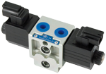
Valve elements with 4 ways and 3, or 2, positions.

Control spools directly operated by solenoids with removable coils.

In the de-energized condition, the control spool is held in the central position by return springs.

Wet pin tubes for DC coils, with push rod for mechanical override; burnish surface treatment.

Coils can be rotated 360° around the tube.

Manual override (push-button or screw type) available as option.

Size 4

Series 00

Maximum operating pressure 310 bar (4500 psi)

Maximum flow 25 l/min (6.6 gpm)

Port connections G 3/8 SAE6 - M16x1.5

RE18300-52-order
RE18300-52-sym

1) The required hydraulic symbol and spool variant can be chosen by consulting page 3.

2) For connectors ordering code see data sheet RE 18325-90.

3) Without secondary valve (versions B80__; B84__), the standard configuration corresponds to “0”.

The secondary valves have a maximum flow capacity of 6 l/min (1.6 gpm).

RE18300-52-spool
RE18300-52-Functional

The sandwich plate design directional valve elements B8_08… are very compact direct operated solenoid valves which control the start, the stop and the direction of the oil flow. These elements basically consist of a stackable housing (1) with a control spool (2), one or two solenoids (5), and one or two return springs (4). When energized, the force of the solenoid (5) pushes the control spool (2) from its neutral-central position “0” to the required end position “a” or “b”, and the required flow from P to A (with B to T), or P to B (with A to T) is achieved. Once the solenoid is de-energized, the return spring (4) pushes the spool thrust washer (3) back against the housing and the spool returns in its neutral-central position.

Each coil is fastened to the solenoid tube by a ring nut (6). A pin (7) allows to push the spool (2) in emergency conditions, when the solenoid cannot be energized, like in case of voltage shortage.

Code
Voltage [V]
Connector type
Coil description
Marking
Coil Mat no.
=OB 01
12 DC
EN 175301-803 (Ex. DIN 43650)
C3601 12DC
12 DC
R933000044
=OB 03
12 DC
AMP JUNIOR
C3603 12DC
12 DC
R933000047
=OB 04
12 DC
AMP JUNIOR Horizontal
C3604 12DC
12 DC
R933002913
=OB 07
12 DC
DEUTSCH DT 04-2P
C3607 12DC
12 DC
R933000048
=OB 31
12 DC
Cable 350 mm long
C3631 12DC
12 DC
R933000045
=AD 01
13 DC
EN 175301-803 (Ex. DIN 43650)
C3601 13DC
13 DC
R933000051
=AD 07
13 DC
DEUTSCH DT 04-2P
C3607 13DC
13 DC
R933000049
=OC 01
24 DC
EN 175301-803 (Ex. DIN 43650)
C3601 24DC
24 DC
R933000053
=OC 03
24 DC
AMP JUNIOR
C3603 24DC
24 DC
R933000057
=OC 04
24 DC
AMP JUNIOR Horizontal
C3604 24DC
24 DC
R933002914
=OC 07
24 DC
DEUTSCH DT 04-2P
C3607 24DC
24 DC
R933000058
=OC 31
24 DC
Cable 350 mm long
C3637 24DC
24 DC
R933000055
=AC 01
27 DC
EN 175301-803 (Ex. DIN 43650)
C3601 27DC
27 DC
R933000056
=AC 07
27 DC
DEUTSCH DT 04-2P
C3607 27DC
27 DC
R933000050
=OD 01
48 DC
EN 175301-803 (Ex. DIN 43650)
C3601 48DC
48 DC
R933000059
=OD 04
48 DC
AMP JUNIOR Horizontal
C3604 48DC
48 DC
R933002915
=OE 01
110 DC
EN 175301-803 (Ex. DIN 43650)
C3601 110DC
110 DC
R933000061
=OV 01
24 RAC
EN 175301-803 (Ex. DIN 43650)
C3601 21.5DC
21.5 DC
R933000054
=OW 01
110 RAC
EN 175301-803 (Ex. DIN 43650)
C3601 98DC
98 DC
R933000060
=OZ 01
230 RAC
EN 175301-803 (Ex. DIN 43650)
C3601 207DC
207 DC
R933000062
General
Valve element with 2 solenoids:
  • 1.34 kg (2.95 lbs)
Valve element with 1 solenoid:
  • 1.06 kg (2.34 lbs)
Fluid Temperature:
  • –20….+50 (-4….+122) (NBR seals)
MTTFd:
  • 150 years see RE 18350-51
Hydraulic
Maximum pressure at P, A and B ports:
  • 310 bar (4500 psi)
Maximum pressure at T:
  • 250 bar (3625 psi)
Maximum inlet flow:
  • 25 l/min (6.6 gpm)
Maximum inlet flow with spool A201:
  • 20 l/min (5.3 gpm)
Hydraulic fluid General properties: it must have physical lubricating and chemical properties suitable for use in hydraulic systems such as, for example:
  • Mineral oil based hydraulic fluids HL (DIN 51524 part 1). Mineral oil based hydraulic fluids HLP (DIN 51524 part 2). For use of environmentally acceptable fluids (vegetable or polyglycol base) please consult us.
Fluid Temperature:
  • –20….+80 °C (-4….+176 °F) (NBR seals)
Permissible degree of fluid contamination:
  • ISO 4572: βₓ≥75 X=12…15 ISO 4406: class 20/18/15 NAS 1638: class 9
Viscosity range:
  • 5….420 mm²/s
Electrical
Voltage type:
  • DC (AC only with RAC connection)
Voltage tolerance (nominal voltage):
  • -10 …. +10 %
Duty:
  • Continuous, with ambient temperature ≤ 50°C (122°F)
Coil wire temperature not to be exceeded:
  • 150 °C (302 °F)
Insulation class:
  • H
Compliance with:
  • Low Voltage Directive LVD 73/23/EC (2006/95/EC), 2004/108/EC
Coil weight with connection EN 175301-803:
  • 0.215 kg (0.44 lbs)
Voltage:
  • 12 V
  • 13 V
  • 24 V
  • 27 V
  • 48 V
  • 110 V
  • 24 V +RAC (21,5)
  • 110 V +RAC (98)
  • 230 V +RAC (207)
Voltage type:
  • DC
  • DC
  • DC
  • DC
  • DC
  • DC
  • DC
  • DC
  • DC
Power consumption:
  • 26 W
  • 26 W
  • 26 W
  • 26 W
  • 26 W
  • 26 W
  • 29 W
  • 29 W
  • 29 W
Current (nominal at 20 °C (68 °F)):
  • 2.15 A
  • 2.0 A
  • 1.10 A
  • 1.0 A
  • 0.54 A
  • 0.27 A
  • 1.20 A
  • 0.29 A
  • 0.14 A
Resistance (nominal at 20 °C (68 °F)):
  • Note: For applications with different specifications consult us
  • 5.5 Ω
  • 6.5 Ω
  • 22 Ω
  • 28 Ω
  • 89 Ω
  • 413 Ω
  • 18 Ω
  • 338 Ω
  • 1430 Ω
RE18300-52-02
Spool Variant
Curve no.
P>T
P>A
P>B
A>T
B>T
B201
 
3
3
2
2
E201
 
3
3
4
4
A201
2
1
1
1
1
C201
4
4
4
4
4
K201
 
3
3
4
3
X301
 
2
3
3
2
Y301
 
2
3
3
2

Measured with hydraulic fluid ISO-VG32 at 45° ±5 °C (113° ±9 °F); ambient temperature 20 °C (68 °F).

RE18300-52-Performance
Spool Variant
Curve no.
B201
1
E201
1
A201
4
C201
1
K201
3
X301
1
Y301
2

The performance curves are measured with flow going across and coming back, like P>A and B>T, with symmetrical flow areas.

In case of special circuit connections, the performance limits can change.

RE18300-52-Minimum-flow
RE18300-52-Lowest-pressure-setting
Secondary valve setting
Curve no.
50-210 bar (700-2950 psi)
0
100-310 bar (1400-4500 psi)
1
25-50 bar (350-700 psi)
2
RE18300-52-dim
1
Solenoid tube Ø 14 mm (0.55 inch).
2
Ring nut for coil locking (OD 20.5 mm); torque 3-4Nm (2.2-3 ft-lb).
3
Identification label.
4
Clearance needed for connector removal.
5
Optional push-button manual override, EP type, for spool opening: it is pressure stuck to the ring nut for coil locking. Mat no. R933000042.
6
Optional screw type manual override, EF type, for spool opening: it is screwed (torque 6-7 (4.4-5.2 ft-lb)) to the tube as replacement of the coil ring nut. Mat no. R933006377.
7
Flange specifications for coupling to ED intermediate elements.
8
For tie rod and tightening torque information see data sheet RE 18301-90.
9
O-Rings for P and T ports.
10
Space needed for secondary valve.
11
A and B ports.
RE18300-52-Electric-connection