Compact Directional Valves - Non-compensated and Post-compensated - Directional elements EDC Series

EDC-Z

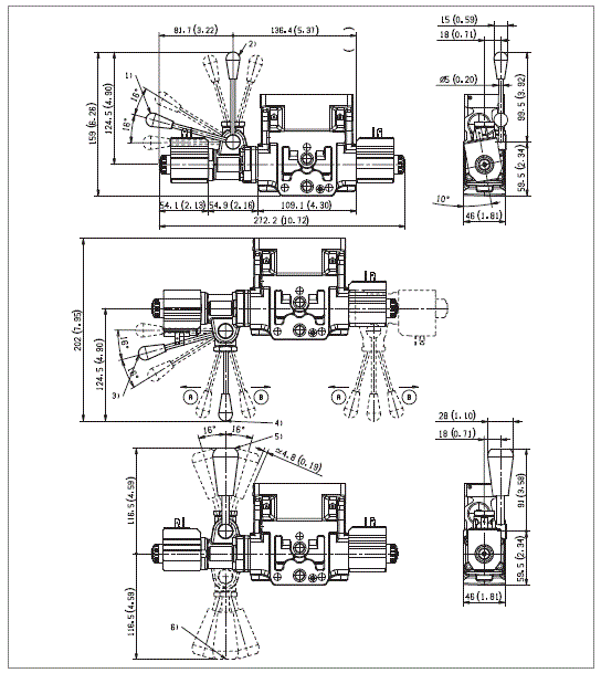
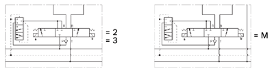
  • Valve element with direct on-off flow sharing control.
  • It can achieve multiple simultaneous manoeuvres by distributing the available flow to each actuator selected by the operator, independently from the working pressure required.
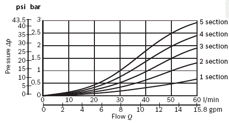
  • All simultaneous movements go on at the same reduced speed in case of flow shortage.
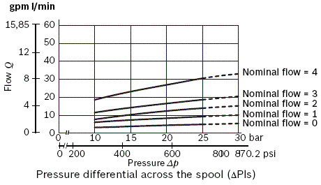
  • Each energized actuator receives a pressure compensated flow.

No shuttle valve fitted.

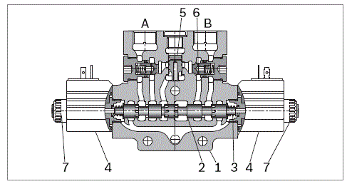
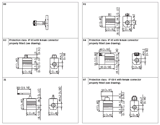
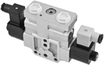
Control spools directly operated by screwed-in solenoids with removable coils.

Wet pin tubes for DC coils, with push rod for mechanical override; nickel plated surface.

Manual override (push-button, screw type or lever) available as option.

Different plug-in connectors available: see ordering details.
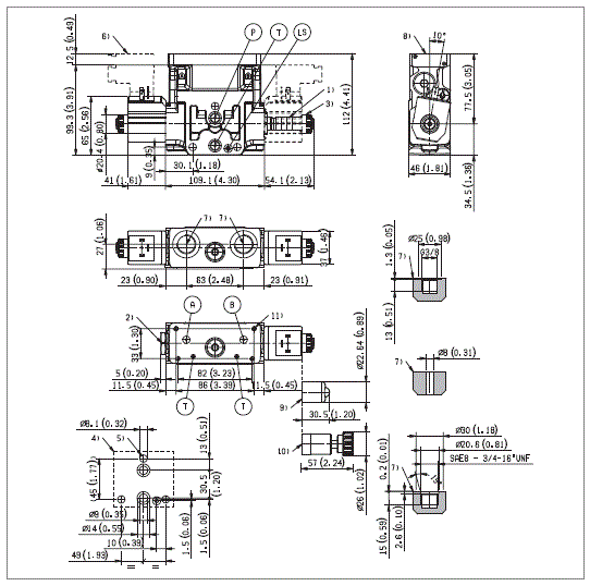
Size 6

Series 00

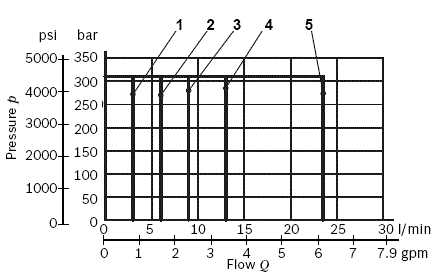
Maximum operating pressure 310 bar (4500 psi)

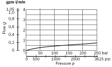
Maximum flow at 14 bar (203 psi) 23.5 l/min (6.2 gpm)

Maximum flow at 18 bar (261 psi) 26.5 l/min (7 gpm)

Ports connections G 3/8 - SAE8 and Modular

NEW spool position sensor available for this valve.

See RE18300-30

RE18301-10-order

Symbols

RE18301-10-sym

Spool variant and Flow pattern

RE18301-10-spool
RE18301-10-functional

The sandwich plate design directional valve elements L8510… are compact direct operated pressure compensated solenoid valves which control the start, the stop, the direction and the quantity of the oil flow, with a FLOW SHARING principle. These elements basically consist of a stackable housing (1) with a control spool, two solenoids (4), two return springs. When energized, each solenoid (4) displaces the control spool from its neutralcentral position “0” and the metering notches are open; flow is delivered to the 3 way pressure compensator followed by a check valve for each port A and B. The compensator, balanced by the LS pressure at the opposite end, lifts up and unloads a pressure compensated flow which is sent to the A (or B) port through the relevant check valve; at the same time the opposite port allows oil return to tank.

LS pressure reaches the compensator “dead end” directly from the A or B port, while the check valves lock eventual pressure oscillations which could affect the compensator function.

When the solenoid is de-energized, the return spring pushes the spool thrust washer back against the housing and the spool returns in its neutral-central position.

Each coil (4) is fastened to the solenoid tube by a ring nut (7). A pin allows to push the spool under emergency conditions, when the solenoid cannot be energized, like in case of voltage shortage.

Code

Voltage [V]

Connector type

Coil description

Marking

Coil Mat no.

OB 01

12 DC

EN 175301-803

(Ex. DIN 43650)

C3601 12DC

12 DC

R933000044

OB 03

12 DC

AMP JUNIOR

C3603 12DC

12 DC

R933000047

OB 04

12 DC

AMP JUNIOR Horizontal

C3604 12DC

12 DC

R933002913

OB 07

12 DC

DEUTSCH DT 04-2P

C3607 12DC

12 DC

R933000048

OB 31

12 DC

Cable 350 mm long

C3631 12DC

12 DC

R933000045

AD 01

13 DC

EN 175301-803

(Ex. DIN 43650)

C3601 13DC

13 DC

R933000051

AD 07

13 DC

DEUTSCH DT 04-2P

C3607 13DC

13 DC

R933000049

OC 01

24 DC

EN 175301-803

(Ex. DIN 43650)

C3601 24DC

24 DC

R933000053

OC 03

24 DC

AMP JUNIOR

C3603 24DC

24 DC

R933000057

OC 04

24 DC

AMP JUNIOR Horizontal

C3604 24DC

24 DC

R933002914

OC 07

24 DC

DEUTSCH DT 04-2P

C3607 24DC

24 DC

R933000058

OC 31

24 DC

Cable 350 mm long

C3637 24DC

24 DC

R933000055

AC 01

27 DC

EN 175301-803

(Ex. DIN 43650)

C3601 27DC

27 DC

R933000056

AC 07

27 DC

DEUTSCH DT 04-2P

C3607 27DC

27 DC

R933000050

OD 01

48 DC

EN 175301-803

(Ex. DIN 43650)

C3601 48DC

48 DC

R933000059

OD 04

48 DC

AMP JUNIOR Horizontal

C3604 48DC

48 DC

R933002915

OE 01

110 DC

EN 175301-803

(Ex. DIN 43650)

C3601 110DC

110 DC

R933000061

OV 01

24 RAC

EN 175301-803

(Ex. DIN 43650)

C3601 21.5DC

21.5 DC

R933000054

OW 01

110 RAC

EN 175301-803

(Ex. DIN 43650)

C3601 98DC

98 DC

R933000060

OZ 01

230 RAC

EN 175301-803

(Ex. DIN 43650)

C3601 207DC

207 DC

R933000062

General
Valve element with 2 solenoids:
  • 3.42 kg (7.54 lbs)
Valve element with 1 solenoid:
  • 2.81 kg (6.19 lbs)
Fluid Temperature:
  • –20.... +50 (-4.... +122) (NBR seals)
MTTFd:
  • 150 years se RE18350-51
Hydraulic
Maximum pressure at P, A and B ports:
  • 310 bar (4500 psi)
Maximum pressure at T:
  • 210 bar (3050 psi)
Maximum pressure with lever emergency at T:
  • 140 bar (2030 psi)
Max. regulated flow at 14 bar (203 psi):
  • 23,5 l/min (6.2 gpm)
Max. regulated flow at 18 bar (261 psi):
  • 26.5 l/min (7 gpm)
Hydraulic fluidGeneral properties: it must have physical lubricating and chemical properties suitable for use in hydraulic systems such as, for example:
  • Mineral oil based hydraulic fluids HL (DIN 51524 part 1). For use of environmentally acceptable fluids (vegetable or polyglycol base) please consult us.
Fluid Temperature:
  • –20.... +80 °C (-4.... +176°F) (NBR seals)
Permissible degree of fluid contamination:
  • ISO 4572: βₓ≥75 X=12...15 NAS 1638: class 9
Viscosity range:
  • 5.... 420 mm²/s
Electrical
Voltage type:
  • DC (AC only with RAC connection)
Voltage tolerance (nominal voltage):
  • -10 .... +10%
Duty:
  • Continuous, with ambient temperature ≤ 50°C (122°F)
Coil wire temperature not to be exceeded:
  • 150°C (302°F)
Insulation class:
  • H
Compliance with:
  • Low Voltage Directive LVD 73/23/EC (2006/95/EC), 2004/108/EC
Coil weight:
  • 0.215 kg (0.44 lbs)
Voltage:
  • 12 V
  • 13 V
  • 24 V
  • 27 V
  • 48 V
  • 110 V
  • 24+RAC (21,5) V
  • 110 (98)+RAC V
  • 230+RAC (207) V
Voltage type:
  • DC
  • DC
  • DC
  • DC
  • DC
  • DC
  • AC
  • AC
  • AC
Power consumption:
  • 26 W
  • 26 W
  • 26 W
  • 26 W
  • 26 W
  • 26 W
  • 29 W
  • 29 W
  • 29 W
Nominal 100% current:
  • 2.15 A
  • 2.00 A
  • 1.10 A
  • 1.10 A
  • 0.54 A
  • 0.27 A
  • 1.20 A
  • 0.29 A
  • 0.14 A
Coil resistance (nominal at 20°C (68°F)):
  • Note: For applications with different specifications consult us
  • 5.5 Ω
  • 6.5 Ω
  • 22 Ω
  • 28 Ω
  • 89 Ω
  • 413 Ω
  • 18 Ω
  • 338 Ω
  • 1430 Ω

Nominal flow Qnom=Qnom (ΔP ls)

RE18301-10-nom-flow

LS drain

RE18301-10-ls-drain

Version: pressure drop Δp = Δp(Q) (PIN- POUT) to the next section

RE18301-10-press-drop

Pressure drop Δp = Δp(Q) with spool B2S4

RE18301-10-press-drop2

Performances limits

RE18301-10-perf-limits
Spool Variant
Curve no.
B2S0, E2S0, B3S0, E3S0, B4S0, E4S0, B2I0, E2I0, B3I0, E3I0, B4I0, E4I0
1
B2S1, E2S1, B3S1, E3S1, B4S1, E4S1, B2I1, E2I1, B3I1, E3I1, B4I1, E4I1
2
B2S2, E2S2, B3S2, E3S2, B4S2, E4S2, B2I2, E2I2, B3I2, E3I2, B4I2, E4I2
3
B2S3, E2S3, B3S3, E3S3, B4S3, E4S3, B2I3, E2I3, B3I3, E3I3, B4I3, E4I3
4
B2S4, E2S4, B3S4, E3S4, B4S4, E4S4, B2I4, E2I4, B3I4, E3I4, B4I4, E4I4
5
The performance curves are measured with flow going across and coming back, like P>A and B>T. With “lever type” emergency control, the performance limits are slightly lower.
RE18301-10-dim
1
Solenoid tube Ø 14 mm (0.55 inch).
2
Plug for 2 positions versions (4/2).
3
Ring nut for coil locking (Ø 20.4 mm).Torque 5-6Nm (3.6-4 4 ft-lb).
4
Flange specifications for coupling to ED intermediate elements.
5
For tie rod and tightening torque information see data sheet RE 18301-90.
6
Clearance needed for connector removal.
7
A and B ports.
8
Identification label.
9
Optional push-button manual override, 0P type, for spool opening: it is pressure stuck to the ring nut for coil locking.Mat no. R933000042.
10
Optional screw type manual override, 0F type, for spool opening: it is screwed (torque 6-7 Nm (4.4-5.2 ft-lb)) to the tube as replacement of the coil ring nut. Mat no. R933000021.
11
Four threaded holes M5 deepth 12mm (0.47 inch) for fitting a secondary flangeable element. Bolts M5 with recommended strength class DIN8.8: torque 5-6 Nm (3.6-4.4 ft-lb) (only for version with modular secondary valves).

RE18301-10-dim2
1
Ordering Details: HA (if fitted to side A) or HB (if fitted to side B)
2
Ordering Details: VA (if fitted to side A) or VB (if fitted to side B)
3
Ordering Details: H1 (if fitted to side A) or H9 (if fitted to side B)
4
Ordering Details: V1 (if fitted to side A) or V9 (if fitted to side B)
5
Ordering Details: XA (if fitted to side A) or XB (if fitted to side B)
6
Ordering Details: X1 (if fitted to side A) or X9 (if fitted to side B)
RE18301-10-elec-conn