Compact Motion Control Valves - Flow Control Valves - Flow regulator

A-VRFC3C-VEI-VS-LS

RE18309-63-01(2023-11-20)
Description

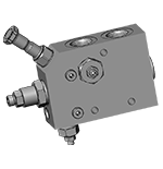
The flow control valves series “A-VRFC3C-VEI-VS” are 3 way, with one inlet “P” and two outlets “A” and “B”, the first outlet “A” being priority, pressure compensated type, with pressure relief valve and available on demand through a solenoid cartridge; the second outlet “B” is the by-pass for all flow in excess of what demanded by priority. Both flows from “A” and “B” ports can be employed to power different functions of the machine. A pressure signal “LS” from the valve is delivered to the load sensing circuit to increase the pump flow in order to match the requirement. These valves provide a simple and efficient way to power hydraulic tools (such as hydraulic hammers) from the existing hydraulic system, without any need to modify the directional control valve. They allow the simultaneous operations, independently from the respective working pressures, of both the hydraulic actuator powered by the priority outlet “A”, and of the normal functions of the machine (traction, slewing, cylinder motions, etc.) supplied by the main directional valve through the by-pass outlet “B”.

General:
Max. operating pressure:
  • 350 bar (5000 psi)
Max. priority line pressure: limited by relief valve (6). See “priority pressure range”:
Back pressure at T port:
  • max. 1.5 bar (20 psi)
Drain from T, with solenoid valve non-energized:
  • up to 1.5 l/min. (0.4 gpm)
Weight:
  • See “Dimensions”
Manifold material:
  • Zinc plated steel
Fluid:
  • Mineral oil (HL, HLP) according to DIN 51524
Fluid temperature range:
  • -20 °C to 80 (-4 to 176 °F)
Viscosity range:
  • 20 to 380 mm2/s (cSt)
Recommended degree of fluid contamination:
  • Class 19/17/14 according to ISO 4406
Other technical data:
  • Note: Note: for applications outside these parameters, please consult us.
  • see data sheet 18350-50
RE18309-63-order(2023-11-20)
RE18309-63-02(2023-11-20)
RE18309-63-dim(2023-11-20)
29 (1.14)
5 (0.2)
50 (1.97)
36.5 (1.44)
32 (1.26)
49 (1.93)
61 (2.4)
34 (1.34)
50 (1.97)
140 (5.51)
75 (2.95)
13.5 (0.53)
73 (2.87)
13.5 (0.53)
68 (2.68)
42 (1.65)
30 (1.18)
100 (3.93)
9 (0.35)
1 1/16- 12 UN-2B
6 (13)
S2
S1
S
L6
L5
L4
L3
L2
L1
L
I
H6
H5
H4
H3
H2
H1
H
F
Port sizes
Weight kg (lbs)

When positioning and tightening the valve, avoid any deflection of the body which could prevent the internal spool from sliding freely and impair the metering performance; it is recommended to use the 3 available fixation holes as locating points and to fit 3 equal spacers (metal washers), one on each point, between the valve body and the supporting structure.

Connections to the hydraulic system:

  • Port “P” (inlet) to the main line from the pump.
  • Port “A” (priority outlet) to the line feeding the hydraulic hammer, or the attachment. Important: for the correct metering of the compensating spool the priority outlet shall be always pressurized, with a back-pressure of at least 8-9 bar (115-130 psi); if necessary, fit a check valve with the needed cracking pressure.
  • Port “B” (by-pass, or excess flow outlet) to the line delivering the oil to the main directional valve.
  • Port “T” to a tank line. It is absolutely necessary that port “T” is connected to a low pressure tank line, 1-1.5 bar max (15-22 psi max).
  • Port “LS” to the load sensing line
RE18309-63-03(2023-11-20)
Port sizes A - B
Cracking pressure bar (psi)
Dimensions mm (inches)
Ordering code
C
L
L1
1 1/16-12 UN-2B
8 (115)
36 (1.42)
69 (2.72)
16 (0.63)
043117005701000 R930000453

The volume of priority flow from port “A” can be easily modified by turning the screw (1): the flow increases by turning the screw counter-clockwise and, once adjusted to the desired level, it remains constant independently from the working pressure.

Adjustment of maximum priority pressure

The maximum pressure in the priority line “A” can be adjusted by turning the screw (5) of the small relief cartridge (6) which controls the maximum pressure in the chamber (3): when this “pilot” cartridge opens, the pressure in chamber (3) drops and the priority flow is stopped.

Note: the relief cartridge (6) controls only the maximum pressure in the priority outlet “A”, and does not control the pressure in the by-pass and main line: the main line must be protected by another relief valve, capable to discharge the full oil flow.

Note: please refer to data sheet RE 18325-90 for coils and connectors readily available and for further details.


Ordering code: OD.02.36 - X - Y - Z

RE18309-63-04(2023-11-20)

Attention: indicated coils fit every hammer valve versions

TECHNICAL DATA

Weight: 0.18 kg (0.40 lbs)

Power: 20 W

Heat insulation Class H: 180°C (356°F)

Ambient temperature range: -30/+90°C (-22/+194°F)

Further performance limits in terms of temperature and voltage fluctuations: please refer to data sheet of the solenoid valve where D36 coil is mounted.

X
Y
Connections
Circuit
Voltage
01
30
DIN 43650 - ISO 4400
Standard
DC
07
30
AMP JUNIOR H
Standard
DC
07
3P
AMP JUNIOR V
Standard
DC
14
30
DIN 43650 - ISO 4400
Bidirectional Diode
DC
15
30
AMP JUNIOR H
Bidirectional Diode
DC
15
3P
AMP JUNIOR V
Bidirectional Diode
DC

RE18309-63-05(2023-11-20)
X
Y
Connections
Circuit
Voltage
20
30
DEUTSCH DT04-2P-L
Standard
DC
20
3P
DEUTSCH DT04-2P-V
Standard
DC
30
3P
AMP SUPERSEAL-V
Standard
DC
22
30
DEUTSCH DT04-2P-L
Bidirectional Diode
DC
22
3P
DEUTSCH DT04-2P-V
Bidirectional Diode
DC
32
3P
AMP SUPERSEAL-V
Bidirectional Diode
DC

RE18309-63-06(2023-11-20)
X
Y
Connections
Circuit
Voltage
0G
03
SINGLE LEAD *
Standard
DC
02
03
FLYING LEAD **
Standard
DC
03
30
KOSTAL M27x01
Standard
DC
40
3P
METRIPAK
Standard
DC
0H
03
SINGLE LEAD *
Bidirectional Diode
DC
23
03
FLYING LEAD **
Bidirectional Diode
DC
12
30
KOSTAL M27x01
Bidirectional Diode
DC
41
3P
METRIPAK
Bidirectional Diode
DC

* Lenght 300mm (11.8 inches). Ext. diameter 6.3mm (0.25 inches). External and internal Shealth Silicone rubber.

** Lenght 300mm

Note: Single lead and Flying lead coil also available with 1000 mm lenght; ordering code with Y=10 in place of Y=03

Z
Voltage V
Resistance Ohm (±7%)
Power W
Current A
Nominal
aT = 20 °C (68 °F)
 
I Max.
I Nom.
OB
12 DC
7.4
20
1.67
1.04
OC
24 DC
28.4
20
0.83
0.54
OD
48 DC
106.5
20
0.42
0.29
OU*
96 DC
451
20
0.21
0.14
AH*
205 DC
2062
20
0.10
0.06

* OU and AH versions especially designed in cases of AC supply voltage (respectively for 110AC and 220 AC) to be used in conjunction with connector with circuit including wave rectifier.

Ambient temperature range for OU and AH versions: -30°C / + 75°C

Diode set at 27 V DC for 12 V DC coil and at 39 V DC for 24 V DC coil.

SOLENOID CARTRIDGE
Port size
Ordering code
0M.43.21.80.57.20
OD150218A000000 R930059442
0M.43.21.80.57.35
RELIEF CARTRIDGE
Port size
Ordering code
0M.43.21.80.57.20
041149035620000 R901097728
0M.43.21.80.57.35
041149035635000 R901091914