Sleeve for Line Mounting - Directional Control Valves - Check

VU-MF (G 1/2-G 3/4)

RE18316-36-01(2023-11-27)
RE18316-36-02(2023-11-27)

Δp curves vs. flow in “A-B” free flow direction

For cracking pressure range refer to the specific table.

Description

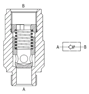
Flow is always allowed to pass from A to B when pressure at A rises above the spring bias pressure and the poppet is pushed from the seat. The valve is normally closed (checked) from B to A. Precision machining and hardening processes allow virtually leak free performance in the checked condition.

Steel body, zinc plated
General:
Ports:
  • Pressure P max bar (psi)
G 1/2:
  • 350 (5000)
G 3/4:
  • 350 (5000)
RE18316-36-dim(2023-11-27)
Springs
Z
Cracking presure
Ordering code
Ordering code
bar
psi
Y=03
Y=04
01
8
116
03.51.01.428
03.51.01.450
  • Very compact design and inline mounting for space saving.
  • Four sizes (see also next page) provide great adaptability to the system.
  • Mounting position is unrestricted.
  • Very low Δp in the free flow direction.
RE18316-36-order(2023-11-27)
Y
Ports A - B
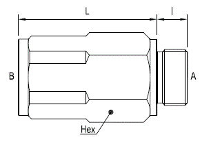
L mm (inches)
I mm (inches)
Hex mm (inches)
03
G 1/2
57 (2.24)
14 (0.55)
30 (1.18)
04
G 3/4
69 (2.72)
16 (0.63)
36 (1.42)