- Compact design and inline mounting for space saving.
- Mounting position is unrestricted
- The inserted flow regulator cartridge can be purchased separately for easy service or for modifications to the original flow adjustment (see data sheet RE 18329-80).
VCDC-H-MC (G 1/4-G 3/8)
![]() Note: the inserted flow regulator cartridge is available with a number of different orifices for different flow ranges, as specified by the “Z” table: when ordering please specify the needed Flow Range (“Z table”), as well as the needed Port Size (“Y table”). Customer tailored flow adjustments are available on request: for details, please consult us.
Note: the inserted flow regulator cartridge is available with a number of different orifices for different flow ranges, as specified by the “Z” table: when ordering please specify the needed Flow Range (“Z table”), as well as the needed Port Size (“Y table”). Customer tailored flow adjustments are available on request: for details, please consult us.
Description
This valve is composed by a sleeve with an inserted pressure compensated flow regulator cartridge (VCD1); it controls the oil flow from B to A, and prevents it from exceeding the adjusted value regardless of working pressure, while establishing a minimum pressure differential between 3 bar and 8 bar (45 psi and 115 psi) approximately between the two ports. The inserted cartridge is available in different sizes (as well as the sleeve), and each size is available with different orifices, each one for a specific flow range (see Performance Diagram and Flow Range “Z” table). For each selected size and flow range, the pressure compensated flow can be tuned finely by changing the spring load (see table of Dimensions).
In the reverse direction, A to B, the valve behaves as a fixed restriction, and it allows free flow depending from the pressure available (see Performance diagram).
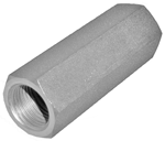
![]() Steel body, zinc plated
Steel body, zinc plated
Special ports available on request.
General:
VCD1 Code:
- Ports A-B
0T.F3.01.02.09...:
- G 1/4
0T.F3.01.02.02...:
- G 3/8
Y
Ports A-B
Lmm (inches)
L1mm (inches)
Hex mm (inches)
Sleeve code
09
G 1/4
66(3.07)
39(1.54)
19(0.75)
OC.51.02.006
02
G 3/8
70(2.76)
42(1.65)
22(0.87)
OC.51.02.007
Z
REGULATED FLOW RANGE l/min (gpm)
G 1/4
G 3/8
G 1/2
G 3/4
01
-
2.5-4.0(0.66-1.06)
16-21(4.23-5.55)
37-50(9.78-13.21)
02
1-1.6(0.26-0.43)
4.0-6.3(1.06-1.67)
21-28(5.55-7.40)
50-67(13.21-17.7)
03
1.6-2.5(0.43-0.66)
6.3-10(1.67-2.64)
28-37(7.40-9.78)
67-90(17.7-23.78)
04
2.5-4.0(0.66-1.06)
10-16(2.64-4.23)
37-50(9.78-13.21)
90-120(23.78-31.7)
05
4.0-6.3(1.06-1.67)
16-25(4.23-6.61)
50-67(13.21-17.7)
120-150(31.7-39.63)
06
6.3-10(1.67-2.64)
-
-
-
Typical applications are the control of the maximum speed of an actuator (double or single acting cylinder, or motor), which is generally achieved by regulating the maximum flow out from the actuator (or meter-OUT). The flow, and consequently the maximum actuator speed, will vary slightly with changes in fluid viscosity, but will be largely independent from the load and from the working pressure.