


SETUP INSTRUCTIONS
Preparation
Make sure that the controller/amplifier is connected to an
operating proportional valve.
For the coil mount version, use a small screwdriver to loosen
the mounting screw and remove the transparent cover. Use a
jeweler’s size screwdriver (slotted 1.5) to make adjustments to the trim pots.
For the metal box style, use a screwdriver to remove the metal cover. Use a small screwdriver to make adjustments to the trim pots.
Interaction Between Maximum Current (I-Max.)
and Minimum Current (I–Min.) Adjustments
• Adjusting the maximum current (I-Max.) does not
affect the minimum current (I-Min.) setting.
• Adjusting the minimum current (I-Min.) will shift the
maximum current (I-Max.) setting.
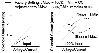
Setting the Minimum Current (I–Min.)
NOTE: Set the minimum current before setting
the maximum current.
The minimum setting can be used to take into account the
mechanical valve deadband and provide desired offsets from
zero to allow full control within the functional range of the
specific valve.
1. Apply appropriate minimum input:
(4mA, 0V or potentiometer, 0V or 0A).
2. The factory setting for the I-Min. trim pot is zero,
fully counterclockwise (CCW).
3. If the desired minimum current is greater than zero,
adjust the trim pot clockwise (CW) until the desired
current is achieved.
Setting the Maximum Current (I–Max.)
1. Apply appropriate maximum control:
(20mA, 5V or control pot at maximum, 10V).
2. Factory setting for the I-Max. trim pot is 100%
or fully clockwise (CW).
3. Turn the trim pot counterclockwise (CCW) to adjust
the current downwards to the desired maximum.
The maximum current setting is adjusted to match the customer’s working pressure or flow range to the full scale signal input range. This provides maximum control for a specific application.
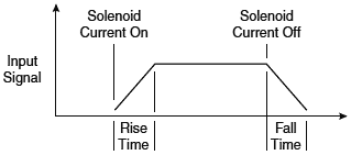
Setting the Ramp Times
1. The factory setting for ramp times is the minimum
(0.01 seconds) or fully CCW.
2. If the ramp time settings are not needed, leave the
settings at the minimum value. (“Economy” version
controllers may have no ramp settings.)
3. To change the ramp times, adjust the trim pot CW to increase the time.
4. Rising (ramp up) and falling (ramp down) times are
independent.
Ramp times are application-dependent. They limit the rate of
change or how fast the operation happens.
NOTE: If the input signal is not applied long enough for the ramp time that has been set, the desired solenoid current will not be reached.
Setting the Dither Amplitude
1. The factory setting for dither amplitude is 0% (CCW).
2. To adjust dither amplitude, turn the trim pot clockwise until
small changes in the input signal register similar changes
in current output.
3. Choose the smallest effective dither amplitude.
(“Economy” version controllers may have no dither
amplitude adjustment.)
Dither amplitude is adjustable from 0 to 10% of rated maximum current. Dither amplitude and frequency are dependent on the specific valve. The effects of static friction on the operation of the solenoid are reduced by the application of a small AC current. The hysteresis and repeatability of the valve are improved by this practice. The optimum dither amplitude is attained when small input signal changes register similar changes in current output (pressure or flow through the valve).
Setting the Dither Frequency
1. The factory setting for dither frequency is the minimum
or 0% (CCW).
2. To adjust dither frequency, turn the trim pot clockwise until
the desired frequency is set.
3. For the dither rating of a particular valve, refer to the valve's catalog specification page.
Start-Up Procedures
1. Make sure that all components, such as the cover,
compression washer, O-ring and base gasket, are correctly
in place (necessary for IP65 protection).
2. Attach the proportional valve amplifier to the load.
3. Switch on the power supply to the controller/amplifier and
apply a control signal.