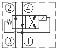
Cartridge Valves - Solenoid Valves - 2-Position 4-Way - Normally Open - Drop-In Cartridges

SV98-T40

SOLENOID CARTRIDGE VALVE 2 POSITION, 4 WAY

Overview

Description

This valve is a direct-acting, spool-type, 2-position, 4-way directional control valve. It is a drop-in, flange mounted, cartridge type valve for use with general purpose hydraulic fluids. Pressure at the tank port (port 1) should not exceed 50 psi [3.4 bar] for proper valve function. The coil is an integral part of the valve and is not serviceable.

Operation

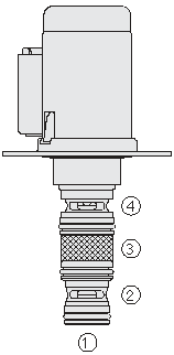
When de-energized, the SV98-T40 allows flow from port 3 to port 2 and from port 4 to port 1. When energized, the cartridge spool shifts to allow flow from port 3 to port 4 and from port 2 to port 1.

Features

  • Economical drop-in style.
  • Integral waterproof coil standard; see page 3.400.1_pdf for a description
  • of tests conducted to verify coil waterproofing.
  • 12 VDC or 24 VDC coils.
  • Several push-on termination options.
Pressure Ratings
Pressure rating:
  • 30 bar (435 psi)
Flow Ratings
Flow rating:
  • 30 lpm (8 gpm)
Maximum internal leakage:
  • 70 ml/min (4.3 in³/min) Max from inlet to tank at and 30 bar (435 psi) 40 °C (248 °F)
Temperature Ratings
Operating fluid temperature:
  • -40 to 149 °C (-40 to 300 °F) HNBR seals
Storage temperature:
  • -40 to 70 °C (-40 to 160 °F)
Ambient temperature:
  • -40 to 90 °C (-40 to 194 °F)
Other Ratings
Corrosion protection:
  • 960 hour Salt-spray
Environmental rating:
  • IP69K Deutsch and Metri-pack
  • IP65 Amp
Response:
  • 50 ms First indication of change of state with 100% voltage and flow rating. Pull-in.
  • 30 ms First indication of change of state with 100% voltage and flow rating. Drop-out.
Minimum pull-in voltage:
  • 80% of nominal voltage At 30 bar (435 psi), at 90 °C (194 °F)
Fluids:
  • Mineral based or synthetic hydraulic fluid with lubricating properties.
Fluid viscosity range:
  • 7.4 to 420 cSt
Maximum operating contamination level:
  • 20/18/14 per ISO4406
Electrical Parameters
Unit weight:
  • 0.26 kg (0.57 lb) Including coil
Internal wetted surface area:
  • 180.13 cm² (27.92 in²)
Valve inductance:
  • 92 mH 12 V coil
  • 276 mH 24 V coil
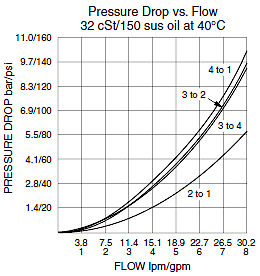
SV98-T40_Perf_Chrt(2022-02-24)
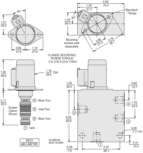
SV98-T40_Dim_Dwg(2022-02-24)
Cavity:
Installation type:
  • Flange mounted (see "drop-in coil outline drawing" for flange options).
Orientation restrictions:
  • None
Mounting screws:
  • M5 X 8, HF P/N: 4000039 (sold separately)
Mounting screw torque:
  • 3 to 4 N-m (2.2 to 3.0 ft-lb)
Seal kit:
  • SK98-T4X X = Seal option
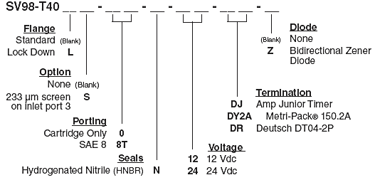
SV98-T40_Order(2022-02-24)

Model Options

SV98-T40DG-H-J-KL
D Flange
CODE
DESCRIPTION
BLANK
Standard
L
Lock Down
G Screen
CODE
DESCRIPTION
BLANK
None
S
142 micron Screen
H Line Body
CODE
DESCRIPTION
0
No Body
8T
Aluminum SAE 8
2B
Aluminum BSPP 1/4" (2)
J Seal
CODE
DESCRIPTION
N
HNBR
K Coil Voltage
CODE
DESCRIPTION
12
12 VDC
24
24 VDC
L Coil Termination
CODE
DESCRIPTION
DJ
D-Coil, AMP Jr.
DJ/Z
D-Coil, AMP Jr. with Zener Diode
DR
D-Coil, Deutsch
DR/Z
D-Coil, Deutsch with Zener Diode
DY2A
D-Coil, Metri-Pack 150.2
DY2A/Z
D-Coil, Metri-Pack 150.2 with Zener Diode