Cartridge Valves - Directional Control Valves - Logic elements

VLSC-10A-8-TF

RE18321-71-01(2023-11-07)
Description

When pressure at 1 rises above the selected spring bias pressure against the spool, the valve shifts to allow block from 2 to 1. Pilot pressure at 3 is additive to the spring bias pressure. The valve may be used in switching or compensation type applications, and will maintain a constant pressure drop across a fixed (or variable) orifice downstream of 1 when installed and piloted per the diagram above.

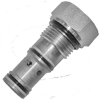
VLSC-10A-8-TF is provided of a damped type spool, especially designed for demanding applications.

¹) Measured at 200 bar (2900 psi)

²) Only external seals for 10 valves

General:
Max. operating pressure:
  • 350 bar (5000 psi)
Max. Flow:
  • 25 l/min. (7 gpm)
Max. internal leakage¹):
  • 50 cm³/min. (3 cu.in./min.)
Fluid temperature range:
  • -30 to 100 °C (-22 to 212 °F)
Installation torque:
  • 41 - 47 Nm (30 - 35 ft-lbs)
Weight:
  • 0.15 kg (0.33 lbs)
Cavity:
  • CA-10A-3C (see data sheet 18325-70)
Lines bodies and standard assemblies:
  • Please refer to section “Hydraulic integrated circuit” or consult factory
Lines bodies and standard assemblies:
  • Please refer to section “Hydraulic integrated circuit” or consult factory
Seal kit²):
  • Code: RG10A9010520100
  • material no: R901111367
Fluids:
  • Mineral-based or synthetics with lubricating properties at viscosities of 10 to 500 mm²/s (cSt)
Recommended degree of fluid contamination:
  • Nominal value max. 10µm (NAS 8) / ISO 4406 19/17/14
Installation:
  • No restrictions
Other Technical Data:
  • See data sheet 18350-50
RE18321-71-02(2023-11-07)
RE18321-71-order(2023-11-07)
RE18321-71-dim(2023-11-07)