Compact Directional Valves - Non-compensated and Post-compensated - Directional elements ED Series

ED2-DZ

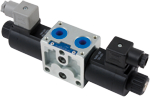
Valve elements with solenoid operated directional spool. Control spools operated by solenoids with removable coils.

In the de-energized condition, the control spool is held in the central position by return springs.

Wet pin tubes for DC coils, with push rod for mechanical override; nickel plated surface.

Coils can be rotated 360° around the tube; they can be energized by AC current through special connectors with rectifier (RAC).

Manual override (push-button or screw type) available as option.

Size 6

Series 00

Maximum operating pressure 310 bar (4500 psi) Maximum flow 50 l/min (13.2 gpm)

Port connections G 3/8 - SAE6 - G 1/2 - SAE8

NEW spool position sensor available for this valve. See RE18300-30

RE18301-02-Order
1
The required hydraulic symbol and spool variant can be chosen by consulting page 3.
2
Available only for A, B, E and F spool configurations. See page 9 for code details.
3
The secondary valves, with maximum flow capacity of 6 l/min (1.6 gpm), are available only for elements with port sizes G 3/8 and SAE 6.
4
Without secondary valves (versions L80 ; L84 ), the standard configuration corresponds to “0”.
5
For connectors ordering code see data sheet RE 18325-90.

Symbols

RE18301-02-sym

Spool variants

RE18301-02-spool
RE18301-02-functional

The sandwich plate design directional valve elements L8_11… are compact direct operated solenoid valves which control the start, the stop and the direction of the oil flow. These elements basically consist of a stackable housing (1) with a control spool (2), one or two solenoids (5), and one or two return springs (4).

When energized, the force of the solenoid (5) pushes the control spool (2) from its neutral-central position “0” to the required end position “a” or “b”, and the required flow from P to A (with B to T), or P to B (with A to T) is achieved. Once the solenoid is de-energized, the return spring (4) pushes the spool thrust washer (3) back against the housing and the spool returns in its neutral-central position.

Each coil is fastened to the solenoid tube by a ring nut (6). A pin (7) allows to push the spool (2) in emergency conditions, when the solenoid cannot be energized, like in case of voltage shortage.

Code
Voltage [V]
Connector type
Coil description
Marking
Coil Mat no.
OB 01
12 DC
EN 175301-803(Ex. DIN 43650)
C4501 12DC
12 DC
R933000026
OB 03
12 DC
AMP JUNIOR
C4503 12DC
12 DC
R933000027
OB 07
12 DC
DEUTSCH DT 04-2P
C4507 12DC
12 DC
R933000030
AD 01
13 DC
EN 175301-803(Ex. DIN 43650)
C4501 13DC
13 DC
R933000028
AD 03
13 DC
AMP JUNIOR
C4503 13DC
13 DC
R933000029
AD 07
13 DC
DEUTSCH DT 04-2P
C4507 13DC
13 DC
R933000031
OC 01
24 DC
EN 175301-803(Ex. DIN 43650)
C4501 24DC
24 DC
R933000034
OC 03
24 DC
AMP JUNIOR
C4503 24DC
24 DC
R933003630
OC 07
24 DC
DEUTSCH DT 04-2P
C4507 24DC
24 DC
R933000032
AC 01
27 DC
EN 175301-803(Ex. DIN 43650)
C4501 27DC
27 DC
R933000035
AC 03
27 DC
AMP JUNIOR
C4503 27DC
27 DC
R933000036
AC 07
27 DC
DEUTSCH DT 04-2P
C4507 27DC
27 DC
R933000033
OD 01
48 DC
EN 175301-803(Ex. DIN 43650)
C4501 48DC
48 DC
R933000037
OE 01
110 DC
EN 175301-803(Ex. DIN 43650)
C4501 110DC
110 DC
R933000040
OV 01
24 RAC
EN 175301-803(Ex. DIN 43650)
C4501 21.5DC
21.5 DC
R933000038
OW 01
110 RAC
EN 175301-803(Ex. DIN 43650)
C4501 98DC
98 DC
R933000039
OZ 01
230 RAC
EN 175301-803(Ex. DIN 43650)
C4501 207DC
207 DC
R933000041
General
Valve element with 2 solenoids:
  • 1.95 kg (4.3 lbs)
Valve element with 1 solenoid:
  • 1.45 kg (3.2 lbs)
Valve element with 2 solenoids, with lever type emergency:
  • 2.2 kg (4.85 lbs)
Valve element with 1 solenoid, with lever type emergency:
  • 1.7 kg (3.75 lbs)
Fluid Temperature:
  • –20....+50 (-4....+122) (NBR seals)
MTTFd:
  • 150 years see RE 18350-51 (NOT VALID for the following schemes: L201,M201,N201,L501,N501,A581,M501)
Hydraulic:
Maximum pressure at P, A and B ports:
  • 310 bar (4500 psi)
Maximum pressure at T:
  • 250 bar (3625 psi)
Max pressure, with lever type emergency at T:
  • 200 bar (2900 psi)
Maximum inlet flow:
  • 50 l/min (13.2 gpm)
Hydraulic fluidGeneral properties: it must have physical lubricating and chemical properties suitable for use in hydraulic systems such as, for example:
  • Mineral oil based hydraulic fluids HL (DIN 51524 part 1). Mineral oil based hydraulic fluids HLP (DIN 51524 part 2). For use of environmentally acceptable fluids (vegetable or polyglycol base) please consult us.
Fluid Temperature:
  • –20....+80 °C (-4....+176 °F) (NBR seals)
Permissible degree of fluid contamination:
  • ISO 4572: βₓ≥75 X=12. 15 NAS 1638: class 9
Viscosity range:
  • 5....420 mm²/s
Electrical
Voltage type:
  • DC (AC only with RAC connection)
Voltage tolerance (nominal voltage):
  • -10 .... +10%
Duty:
  • Continuous, with ambient temperature ≤ 50°C (122°F)
Coil wire temperature not to be exceeded:
  • 150 °C (302 °F)
Insulation class:
  • H
Compliance with:
  • Low Voltage Directive LVD 73/23/EC (2006/95/EC), 2004/108/EC
Coil weight with connection EN 175301-803:
  • 0.335 kg (0.74 lbs)
Voltage:
  • 12V
  • 13V
  • 24V
  • 27V
  • 48V
  • 110V
  • 24 +RAC(21,5)V
  • 110 +RAC(98) V
  • 230 +RAC(207) V
Voltage type:
  • DC
  • DC
  • DC
  • DC
  • DC
  • DC
  • DC
  • DC
  • DC
Power consumption:
  • 33W
  • 31W
  • 33W
  • 33W
  • 33W
  • 35W
  • 33W
  • 33W
  • 35W
Current (nominal at 20 °C (68 °F)):
  • 2.8A
  • 2.3A
  • 1.40A
  • 1.2A
  • 0.7A
  • 0.32A
  • 1.6A
  • 0.34A
  • 0.16A
Resistance (nominal at 20 °C (68 °F)):
  • Note: For applications with different specifications consult us
  • 4.24 Ω
  • 5.42 Ω
  • 17 Ω
  • 21.8 Ω
  • 69.8 Ω
  • 341.8 Ω
  • 13.6 Ω
  • 285 Ω
  • 1229 Ω

RE18301-02-02
Spool Variant
Curve no.
P>T
P>A
P>B
A>T
B>T
A201-A301-A401-A401-A471-A361-G201-G209
2
1
1
1
1
B201-B301-B401-B471-B361-L201-M201-U201-L501-M501
 
4
4
4
4
C201-C301-C401-C471-C361
6
5
5
6
6
D201-D301-D471-D401-D361
 
6
6
5
5
E201-E301-E401-E471-E361-E2R1-T301-T409
 
5
5
6
6
K201-K209-K301-T361-K401-T479
 
5
5
3
3
X301-X401-Y301-Y401
 
4
4
4
4
N301-N201-N401-F201-U361-N501
 
4
4
 

Measured with hydraulic fluid ISO-VG32 at 45° ±5 °C (113° ±9 °F); ambient temperature 20 °C (68 °F).


Performance limits

RE18301-02-performance
Spool Variant
Curve no.
A201-A301-A401-A471-A361- C201-C301-C401-C471-C361-G201-G209 - T301- T401-T479- T361
1
B201-B301-B401-B471-B361- D201-D301-D401-D471-D361 -K201-K209-K301-K401
2
X301-X401-Y301-Y401-M201-L201-U201-U369 -E201-E301-E401-E471-E361-E2R1
3
N301-N401-N201-N501-L501-M501-F201
4

The performance curves are measured with flow going across and coming back, like P>A and B>T. With “lever type” emergency control, the performance limits are slightly lower.


Lowest pressure setting curve for secondary valves

RE18301-02-lowest
Secondary valve setting
Curve no.
50-210 bar (700-2950 psi)
0
100-310 bar (1400-4500 psi)
1
25-50 bar (350-700 psi)
2
50-100 bar (700-2950 psi)
3

RE18301-02-dim1
1
Solenoid tube Ø 19 mm (0.75 inch).
2
Ring nut for coil locking (Ø 26.5 mm); torque 3 – 4 Nm (2.2-3 ft-lb).
3
Flange specifications for coupling to ED intermediate elements with ports G 3/8 and SAE 6.
4
For tie rod and tightening torque information see data sheet RE 18301-90.
5
Flange specifications for coupling to ED intermediate elements with ports G 1/2 and SAE 8.
6
Four threaded holes M5 for fitting a secondary flangeable element (only for elements with ports G 3/8 and SAE 6).Bolts M5 with recommended strength class DIN 8.8: torque 5 – 6 Nm (3.6-4.4 ft-lb).
7
A and B ports.
8
O-Rings for P and T ports.
9
Clearance needed for connector removal.
10
Identification label.

RE18301-02-dim2
11
Flange specifications for coupling to the ED intermediate elements with LS channels (for port sizes G 3/8 and SAE6).
12
For tie rod and tightening torque information see data sheet RE 18301-90.
13
Flange specifications for coupling to the ED intermediate elements with LS channels (for port sizes G 1/2 and SAE 8).
14
Optional push-button manual override, 0P type, for spool opening: it is pressure stuck to the ring nut for coil locking. Mat no. R933000043.
15
Optional screw type manual override, 0F type, for spool opening: it is screwed (torque 6-7 (4.4-5.2 ft-lb)) to the tube as replacement of the coil ring nut. Mat no. R933007215.

External dimensions and fittings

RE18301-02-dim3
1
Ordering Details: HA (if fitted to side A) or HB (if fitted to side B).
2
Ordering Details: VA (if fitted to side A) or VB (if fitted to side B).
3
Ordering Details: H1 (if fitted to side A) or H9 (if fitted to side B).
4
Ordering Details: V1 (if fitted to side A) or V9 (if fitted to side B).
5
Ordering Details: XA (if fitted to side A) or XB (if fitted to side B).
6
Ordering Details: X1 (if fitted to side A) or X9 (if fitted to side B).
RE18301-02