Compact Directional Valves - Non-compensated and Post-compensated - Directional elements ED Series

ED4-P1

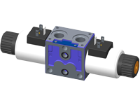
Valve element with direct proportional control of spool. Control spool operated by solenoid with removable coils.

In the de-energized condition, the control spool is held in the central position by return springs.

Wet pin proportional tubes for DC coils, with push rod for mechanical override; nickel plated surface.

Manual override (push-button or screw type) available as option.

Plug-in connectors available: EN 175301-803 (Was DIN 43650) and DT04-2P (Deutsch).

Size 6

Series 00

Maximum operating pressure 310 bar (4500 psi)

Maximum flow 40 l/min (10.5 gpm)

Port connections G 3/8 - G 1/2 - SAE6 - SAE8

NEW spool position sensor available for this valve. See RE18300-30

RE18301-16-order

Symbols

RE18301-16-sym

Spool variants

RE18301-16-01

In neutral position, the valves cross section are as follows:

E_I ≥ 20% of nominal cross section.

E_S ≥ 2% of nominal cross section.

RE18301-16-02

The sandwich plate design directional valve elements L8081… are compact direct operated proportional solenoid valves which control the start, the stop, the direction and the quantity of the oil flow. These elements basically consist of a stackable housing (1) with a control spool (2), one or two solenoids (3), and one or two return springs (4).

Energized by an electronic feed regulator, each solenoid (3) displaces the control spool (2) from its neutral-central position “0” proportionally to the current received; a regulated oil flow P to A, or P to B, is achieved. Once the solenoid is de-energized, the return spring (4) pushes the spool thrust washer (5) back against the housing and the spool returns in its neutral-central position.

Each coil (3) is fastened to the solenoid tube by a ring nut (6). A pin (7) allows to push the spool (2) in emergency conditions, when the solenoid cannot be energized, like in case of voltage shortage.

Code
Voltage [V]
Connector type
Coil description
Marking
Coil Mat no.
=OB 01
12 DC
EN 175301-803(Ex. DIN 43650)
GP45 01 - 45 K4
12 DC
R901022180
=OB 03
12 DC
AMP JUNIOR
GP45 03 - 45 C4
12 DC
R901022680
=OB 07
12 DC
DEUTSCH DT 04-2P
GP45 07 - 45 K40
12 DC
R901272648
=OC 01
24 DC
EN 175301-803(Ex. DIN 43650)
GP45 01 - 45 K4
24 DC
R901022174
=OC 03
24 DC
AMP JUNIOR
GP45 03 - 45 C4
24 DC
R901022683
=OC 07
24 DC
DEUTSCH DT 04-2P
GP45 07 - 45 K40
24 DC
R901272647
General
Valve element with 2 solenoids:
  • 2.20 kg (4.85 lbs)
Valve element with 1 solenoid:
  • 1.70 kg (3.75 lbs)
Fluid Temperature:
  • -30....+90 (-22....+194) (NBR seals)
MTTFd:
  • 150 years see RE 18350-51
Hydraulic
Maximum pressure at P:
  • 310 bar (4500 psi)
Maximum pressure at T:
  • 210 bar (3050 psi)
Maximum inlet flow:
  • 40 l/min (10.5 gpm)
Nominal flow with DP P>T = 10 bar (145 psi):
  • 10, 20, 30, 40 l/min (2.64, 5.28, 7.9, 10.5 gpm)
Hydraulic fluidGeneral properties: it must have physical lubricating and chemical properties suitable for use in hydraulic systems such as, for example:
  • Mineral oil based hydraulic fluids HL (DIN 51524 part 1). For use of environmentally acceptable fluids (vegetable or polyglycol base) please consult us.
Fluid Temperature:
  • -30....+100°C (-22....+212°F) (NBR seals)
Permissible degree of fluid contamination:
  • ISO 4572: βₓ≥75 X=12...15 NAS 1638: class 9
Viscosity range:
  • 20....380 (optimal 30....46) mm²/s
Electrical
Voltage type:
  • 120 Hz PWM
Voltage tolerance (nominal voltage):
  • -10 .... +10%
Duty:
  • Continuous, with ambient temperature ≤ 90°C (194°F)
Coil wire temperature not to be exceeded:
  • 180°C (356°F)
Insulation class:
  • H
Compliance with:
  • Low Voltage Directive LVD 73/23/EC (2006/95/EC), 2004/108/EC
Coil weight:
  • 0.335 kg (0.739 lbs)
Voltage:
  • 12 V
  • 24 V
Nominal 100% current:
  • 1.8 A
  • 1.2 A
Coil resistance(nominal at 20°C (68°F)):
  • Note: For applications with different specifications consult us
  • 3.3 Ω - Cold value
  • 7.2 Ω - Cold value

Nominal Flow = 2

RE18301-16-03

Nominal Flow = 4

RE18301-16-04

Nominal Flow = 6

RE18301-16-05

RE18301-16-dim1
1
Solenoid tube Ø 23 mm (0.9 inch).
3
Ring nut for coil locking (Ø 30 mm);torque 6 – 7 Nm (4.4 – 5.2 ft-lb).
4
Flange specifications for coupling to ED intermediate elements with ports G 3/8 and SAE 6.
5
For tie rod and tightening torque information see data sheet RE 18301-90.
6
Clearance needed for connector removal.
7
A and B ports.
8
Identification label.
9
Optional push-button manual override, 0P type, for spool opening: it is pressure stuck to the ring nut for coil locking. Mat no. R933003424.
10
Optional screw type manual override, 0F type, for spool opening: it is screwed (torque 6-7 (4.4-5.2 ft-lb)) to the tube as replacement of the coil ring nut. Mat no. R930056486.
11
Optional push-button manual override NP (black) and RP (red) type, for spool opening. It is screwed (torque 6-7Nm(4.4-5.2 ft-lb)) to the tube as replacement of the coil ring nut. Mat no. R930056488(black) - R930056489 (red).
12
Optional twist type manual override, 0T type, for spool opening and locking in the energised position. It is screwed (torque 6-7Nm (44-5.2 ft-lb)) to the tube as replacement of the coil ring nut. Mat no. R930056487
13
Four threaded holes M5 for fitting a secondary flangeable element (only for elements with ports G 3/8 and SAE 6). Bolts M5 with recommended strength class DIN 8.8:torque 5 – 6 Nm (3.6-4.4 ft-lb).
14
Flange specifications for coupling to ED intermediate elements with ports G 1/2 and SAE 8.

RE18301-16-dim2
1
Ordering Details: HA (if fitted to side A) or HB (if fitted to side B)
2
Ordering Details: VA (if fitted to side A) or VB (if fitted to side B)
3
Ordering Details: H1 (if fitted to side A) or H9 (if fitted to side B)
4
Ordering Details: V1 (if fitted to side A) or V9 (if fitted to side B)
5
Ordering Details: XA (if fitted to side A) or XB (if fitted to side B)
6
Ordering Details: X1 (if fitted to side A) or X9 (if fitted to side B)
RE18301-16-06
RE18301-16-07

Supply: yellow LED, lit up with power ON.

Off Set: minimum current adjustment. Adjust solenoid current so that the desired minimum value is obtained. Clockwise rotation increases current.

Ramp up: Ramping up time adjustment.

Ramp down: Ramping down time adjustment.

For longer ramping times, turn potentiometers clockwise; for shorter ramping times, turn the potentiometers counter-clockwise.

Full load current: Maximum current adjustment. Adjust solenoid current so that the desired maximum value is obtained (up to 2A). Clockwise rotation increases current.

Frequency adjustment: it is possible to set the PWM frequency obtaining the desired control sensitivity. After removing the external plastic cover, turn the adjusting screw; clockwise rotation increases frequency from 100 to 500 Hz.

Electronic feed regulator
Regulator ordering code
R933003290
Supply voltage
12-30 VDC
Control Signal
0-10 VDC
Max. output current
2 A
Minimum output current
0....0.6 A
Ramp adjustment up/down
0.1....10 s
PWM Frequency adjustment (pre-set 120 Hz)
100....500 Hz
Ambient operating temperature
-10....+60 °C (14....+140 °F)
Weight
0.12 kg (26.4 lbs)
Electromagnetic compatibility
EN50081-1/2EN61000-4-2/3/4/5/6
Protection class with connector and seal correctly fitted and properly screwed down.
IP 65 (DIN40050 part 9)
Potentiometer resistance
5....10 κ Ω