Compact Directional Valves - Pre-compensated - Directional elements EDG series

EDG-DP...B1 - EDG-DP...R1

The inlet section can be configured for either a fixed displacement pump or load-sense variable displacement pump. When simultaneous machine functions are actuated, the pre-compensators will automatically adjust to the highest load pressure via a shuttle arrangement, making the system circuit independent of variations in loads and pump pressures.

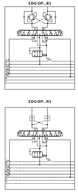
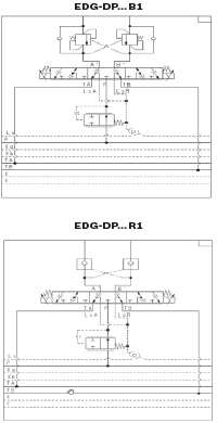
- EDG-DP with Cross Piloted Counterbalance (B1)

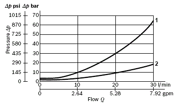
incorporates one or two Cross Piloted Counterbalance valves which allow free flow toward the A and B outlet ports, and lock in a leak free mode the flow returning from the actuator. Pilot pressure in the opposite line reduces the pressure setting of the counterbalance valve in proportion to the pilot ratio (4:1) until opening and allowing the flow return from the actuator. The pressure setting should be at least 1,3 times the highest expected load. Depending on the version selected, the counterbalance function can be double-acting or singleacting (only A ,only B or both A and B ports).

- EDG-DP with Cross Piloted Check Valve (R1)

incorporates one or two Cross Piloted Check Valves which allow free flow toward the A and B outlet ports, and lock in a leak free mode the flow returning from the actuator, until sufficient pilot pressure is built up in the opposite line and the check valve is opened.

Size 6

Series 1

Maximum operating pressure:

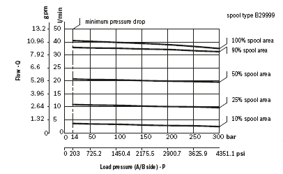
350 bar (5000 psi) on pump side

350 bar (5000 psi) on consumer side

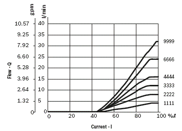
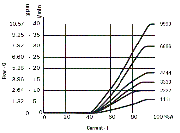
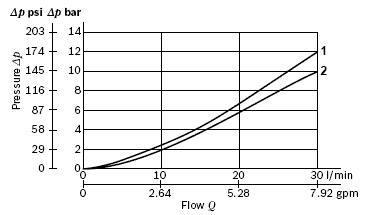
Maximum flow at 6 bar (87 psi) 40 l/min (10.6 gpm)

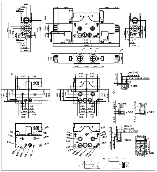
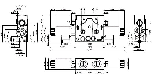
Ports connections G 3/8 - G 1/2 - SAE6 - SAE8

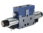
NEW spool position sensor available for this valve.

See RE18300-30

Main Field of Application

Truck mounted applications

Forestry machinery

Forklifts and Telehandler

Municipal vehicles

Cranes

Construction machines

Aerial working platforms

Heavy duty vehicles

Agricultural machines

New Series 1 features:

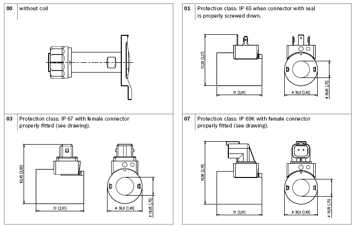
  • Pole tube and coil (emproved corrosion resistance duration up to 500h)
  • Label
  • Flange with drain line for VMGLS and combination for EDG Electrohydraulic actuation
  • Body valve zinc plating treatment for higher corrosion resistence protection up to 500h
RE18301-22-order

Table 1

Notches dimension selection --> Flow Rate
Local compensator bias spring
 
4bar
6bar
1 *
4 l/min
6 l/min
2 *
8 l/min
10 l/min
3 *
12 l/min
14 l/min
4 *
16 l/min
18 l/min
6 **
24 l/min
30 l/min
9 **
32 l/min
40 l/min

*Note: standard spool types (symmetrical): 1111 - 2222 - 3333 - 4444 - 6666 - 9999

** Note: with 6 and 9 spool sizes delta pressure values exceed 30 bar (435 psi)

Table 2

Spool size selection guide
 
P->A(corresponding A->T same size or "I" size)
Notch size
1
2
3
4
6
9
P->B(corresponding B->T same size or "l" size)
1
X
X
2
X
X
X
3
X
X
X
4
X
X
X
6
●●
X
X
X
9
X
X

X = Standard spool flow rate configuration

◊ = Special spool flow rate configuration, contact factory

● = Not available

Table 3 Counterbalance valve configuration setting

9
With valve cavity plugged (Normally closed plug)
A
B
C
D
E
F
G
H
I
J
K
50 bar
60 bar
70 bar
80 bar
90 bar
100 bar
110 bar
120 bar
130 bar
140 bar
150 bar
725 psi
870 psi
1015 psi
1160 psi
1305 psi
1450 psi
1595 psi
1740 psi
1885 psi
2030 psi
2175 psi
L
M
N
O
P
Q
R
S
T
U
V
X
160 bar
170 bar
180 bar
190 bar
200 bar
210 bar
220 bar
230 bar
240 bar
250 bar
270 bar
290 bar
2320 psi
2465 psi
2611 psi
2756 psi
2901 psi
3046 psi
3191 psi
3336 psi
3481 psi
3626 psi
3916 psi
4206 psi

Table 4 R1 secondary valve types

A
9
0,5 bar (7.3 psi)
With valve cavity plugged

Pressure levels are set at 5 l/min (1.32 gpm). For pressure higher than 290 bar (4206 psi), contact factory.


Hydraulic layout

RE18301-22-01

07 Spool Variants

RE18301-22-02
RE18301-22-03

The EDG direct acting proportional solenoid sectional valves with pressure compensation control the oil flow to actuators. These elements consist of a stackable housing (1) with a control spool (2), two solenoids (4), two return springs (3). Each solenoid (4), energized by PWM regulator, displaces the control spool from its neutral-central position “0” proportionally to the current received. When the spool is shifted and the metering notch is open, flow delivery starts and is controlled by a 2 way pressure compensator (7) (P > A; P > B).

When the solenoid is de-energized, the return spring pushes the spool back in its neutral-central position. Each coil (4) is fastened to the solenoid tube by the ring nut (5). A push-pin manual override is included to actuate the valve without electrical power as needed.

Load pressure compensation

The pressure compensator (7) keeps the pressure differential on the main spool (2). The flow to the consumers remains constant, despite varying loads. The highest load pressure on the pump is signaled via the LS line and the integrated shuttle valve (6). Port relief valves with anti-cavitation function on A and B (9) protect the system against pressure peaks and cavitation. LS relief valves (8), for each consumer port, can be adjusted according to specific application requirements.

Code
Voltage [V]
Connector type
Coil description
Marking
Coil Mat no.
=OB 01
12 DC
EN 175301-803 (Ex. DIN 43650)
C37 01
12 DC
R930077022
=OB 03
12 DC
AMP JUNIOR
C37 03
12 DC
R930063954
=OB 07
12 DC
DEUTSCH DT 04-2P
C37 07
12 DC
R930077020
=OC 01
24 DC
EN 175301-803 (Ex. DIN 43650)
C37 01
24 DC
R930077023
=OC 03
24 DC
AMP JUNIOR
C37 03
24 DC
R930063955
=OC 07
24 DC
DEUTSCH DT 04-2P
C37 07
24 DC
R930077021
General
Valve element with 2 solenoids:
  • 2.2 kg (4.85 lbs)
Valve element with 1 solenoid:
  • 1.7 kg (3.75 lbs)
Fluid Temperature:
  • -30….+90 (-22….+194)
Hydraulic
Maximum pressure at P, A and B ports:
  • 350 bar (5000 psi)
Maximum static pressure at T:
  • 210 bar (3050 psi) [in case of Emergency Lever option, max. pressure is limited up to 30 bar at T]
Max. regulated flow at 6 bar (87 psi):
  • 40 l/min (10.6 gpm)
For E schemes symmetrical spool pattern in neutral position (connection A to T and B to T) E-schemes flow pattern with only meter IN (spool type E_ _ _ I I) in neutral position: the opening area is approx the 50% of nominal cross-section. This spool type is suitable in combination with load holding valves applications.:
  • Approx. 2% of the nominal cross-section
Hydraulic fluid General properties: it must have physical lubricating and chemical properties suitable for use in hydraulic systems.:
  • Mineral oil based hydraulic fluids HL (DIN 51524 part 1). For use of environmentally acceptable fluids (vegetable or polyglycol base) please consult us.
Fluid Temperature:
  • -30….+100 °C (-22….+212 °F) (NBR seals)
Permissible degree of fluid contamination:
  • ISO 4572: βₓ≥75 X=12…15 ISO 4406: class 20/18/15 NAS 1638: class 9
Viscosity range:
  • 20….380 mm²/s (optimal 30….46)
Electrical
Voltage type:
  • 120 Hz PWM
Voltage tolerance (nominal voltage):
  • -10 …. +10 %
Duty:
  • Continuous, with ambient temperature ≤ 50°C (122°F)
Coil wire temperature not to be exceeded:
  • 180 °C (356 °F)
Insulation class:
  • H
Compliance with:
  • Low Voltage Directive LVD 73/23/EC (2006/95/EC), 2004/108/EC
Coil weight:
  • 0.228 kg (0.503 lbs)
Voltage:
  • 12 V
  • 24 V
Nominal 100% current:
  • 1.76 A
  • 0.94 A
Nominal Coil Resistance at 20°C (68°F):
  • Note: For applications with different specifications consult us. * In addition to relief valve pressure setting value.
  • 4.05 Ω
  • 13.6 Ω

Characteristic curves Q=Q (I) at 4 bar

RE18301-22-04

2-way inflow controller

RE18301-22-05

Characteristic curve for EDG-DP…B1

RE18301-22-06
Pressure drop
Curve no.
Fully piloted
1
Through check valve
2

Characteristic curves Q=Q (I) at 6 bar

RE18301-22-07

Measured with hydraulic fluid ISO-VG32 at 45° ±5 °C (113° ±9 °F); ambient temperature 20 °C (68 °F).


Characteristic curve for EDG-DP…R1

RE18301-22-08
Cracking Pressure
Curve no.
0.5 bar (7.3 psi) free flow
1
Returning flow, fully piloted
2
RE18301-22-dim1
1
Ring nut for coil locking (Ø 30.3 mm). Torque 6 – 7 Nm (4.4 – 5.2 ft-lb).
2
Flange specifications. For tie rod and tightening torque information see data sheet RE 18301-90.
3
A and B ports.
4
Identification label.
5
Optional push-button manual override, EP type, for spool opening: it is pressure stuck to the ring nut for coil locking. Mat no. R933002705
6
Optional screw type manual override, EF type, for spool opening: it is screwed (torque 6-7 Nm (4.4-5.2 ft-lb)) to the tube as replacement of the coil ring nut. Mat no. R930084529.
RE18301-22-dim2
1
Flow-boost system only for spool with nominal flow 9.It always mounted on "a" side of the valve.
RE18301-22-09