Compact Directional Valves - Stand-alone 4-way directional valves - Size 6 -35 l/min

LC1F-DZ

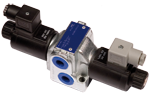
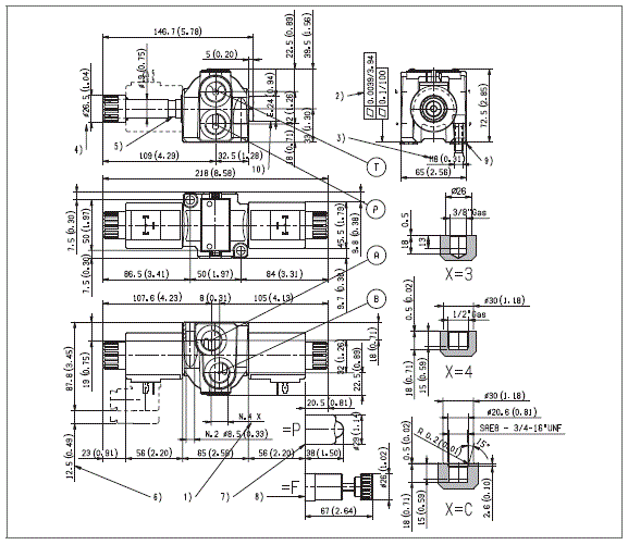
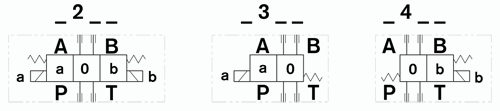
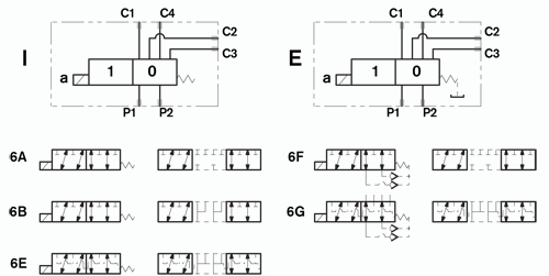
4 way, 2 or 3 position spool type solenoid operated directional valves.

Stand-alone valve body intended for “in-line” application. Available with a choice of threaded ports; mounting surface with installation holes for direct fitting on the machine structure.

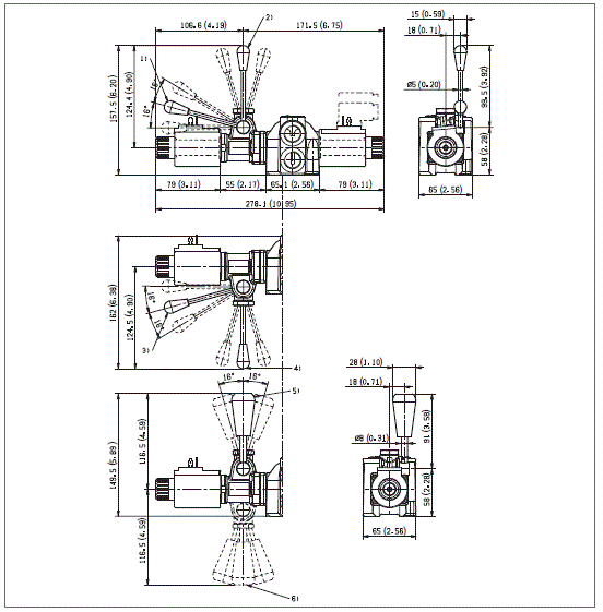
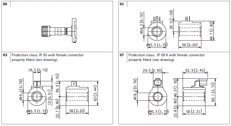
Zinc plated body with yellow trivalent chrome treatment. Wet pin tubes for DC coils, with push rod for mechanical override; nickel plated surface.

Coils can be rotated 360° around the tube; they can be energized by AC current through special connectors with rectifier (RAC).

Plug-in connectors available: EN 175301-803 (was DIN 43650); AMP Junior; DT04-2P (Deutsch), free leads. Coils removable.

Manual override (push button or lever type) available as option.

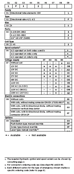
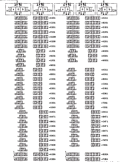
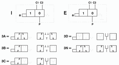
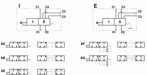
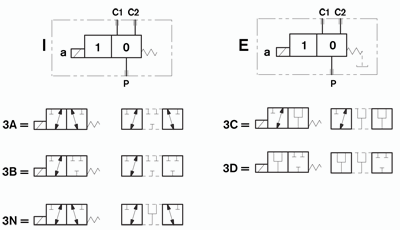
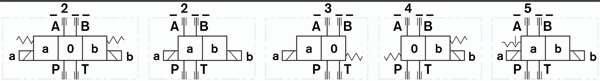
Spool variants (for different hydraulic schemes) are available for both 2 and 3 position versions.

Size 6

Series 00

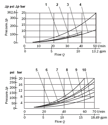
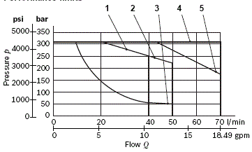
Maximum operating pressure 310 bar (4500 psi)

Maximum flow 70 l/min (18.5 gpm)

Port connections G 3/8 - G 1/2 - SAE8

RE18305-02-order(2023-10-25)

Spool variants

RE18305-02-01(2023-10-25)
RE18305-02-02(2023-10-25)

The directional valves LC1F_DZ are compact direct operated solenoid valves which control the start, the stop, the direction of the oil flow. They basically consist of a housing (1) with a control spool (2), one or two solenoids (5), and one or two return springs (4). When energized, each solenoid (5) displaces the control spool (2) from its neutral-central position to the “a” or “b” position and the oil flow P is diverted to A, or to B.

Once the solenoid is de-energized, the return spring (4) pushes the spool thrust washer back against the housing and the spool (2) returns in its neutral-central position “0”. Each coil is fastened to the solenoid tube (5) by a ring nut (6). A pin (7) allows to push the spool (2) in emergency conditions, when the solenoid cannot be energized, like in case of voltage shortage.

Code
Voltage [V]
Connector type
Coil description
Marking
Coil Mat no.
OB 01
12 DC
EN 175301-803 (Ex. DIN 43650)
C4501 12DC
12 DC
R933000026
OB 03
12 DC
AMP JUNIOR
C4503 12DC
12 DC
R933000027
OB 07
12 DC
DEUTSCH DT 04-2P
C4507 12DC
12 DC
R933000030
AD 01
13 DC
EN 175301-803 (Ex. DIN 43650)
C4501 13DC
13 DC
R933000028
AD 03
13 DC
AMP JUNIOR
C4503 13DC
13 DC
R933000029
AD 07
13 DC
DEUTSCH DT 04-2P
C4507 13DC
13 DC
R933000031
OC 01
24 DC
EN 175301-803 (Ex. DIN 43650)
C4501 24DC
24 DC
R933000034
OC 03
24 DC
AMP JUNIOR
C4503 24DC
24 DC
R933003630
OC 07
24 DC
DEUTSCH DT 04-2P
C4507 24DC
24 DC
R933000032
AC 01
27 DC
EN 175301-803 (Ex. DIN 43650)
C4501 27DC
27 DC
R933000035
AC 03
27 DC
AMP JUNIOR
C4503 27DC
27 DC
R933000036
AC 07
27 DC
DEUTSCH DT 04-2P
C4507 27DC
27 DC
R933000033
OD 01
48 DC
EN 175301-803 (Ex. DIN 43650)
C4501 48DC
48 DC
R933000037
OE 01
110 DC
EN 175301-803 (Ex. DIN 43650)
C4501 110DC
110 DC
R933000040
OV 01
24 RAC
EN 175301-803 (Ex. DIN 43650)
C4501 21.5DC
21.5 DC
R933000038
OW 01
110 RAC
EN 175301-803 (Ex. DIN 43650)
C4501 98DC
98 DC
R933000039
OZ 01
230 RAC
EN 175301-803 (Ex. DIN 43650)
C4501 207DC
207 DC
R933000041
General
Valve element with 2 solenoids:
  • 2.23 kg (4.92 lbs)
Valve element with 1 solenoid:
  • 1.75 kg (3.86 lbs)
Valve element with 2 solenoids, with lever type emergency:
  • 2.53 kg (5.58 lbs)
Valve element with 1 solenoid, with lever type emergency:
  • 2.00 kg (4.41 lbs)
Mounting position:
  • Unrestricted. Horizontal with spool type _5_
Fluid Temperature:
  • −20....+50 (-4....+122) (NBR seals)
Hydraulic
Maximum pressure at P, A and B ports:
  • 310 bar (4500 psi)
Maximum pressure at T ¹:
  • 250 bar (3625 psi)
Maximum pressure on T when using spool type A211, A311, A411:
  • 150 bar (2175 psi)
Max pressure, with lever type emergency at T:
  • 100 bar (1450 psi)
Maximum inlet flow:
  • 70 l/min (18.5 gpm)
Maximum flow when using spool type A201, A301, A361, A401, A471, A2EA, G201, G209:
  • 50 l/min (13.2 gpm)
Maximum flow when using spool type A211, A311, A411 l/min (gpm):
  • 40 l/min (10.6 gpm)
Hydraulic fluidGeneral properties: it must have physical lubricating and chemical properties suitable for use in hydraulic systems such as, for example:
  • Mineral oil based hydraulic fluids HL (DIN 51524 part 1). For use of environmentally acceptable fluids (vegetable or polyglycol base) please consult us.
Fluid Temperature:
  • −20....+80 °C (-4....+176 °F) (NBR seals)
Permissible degree of fluid contamination:
  • ISO 4572: βx≥75 X=12...15 NAS 1638: class 9
Viscosity range:
  • 5....420 mm²/s
Maximum leakage on A and B ports (P and T pressurised) when using A211 type spools:
  • Note: 1) Variation on T line pressure for circuits 5_ with mechanical detent can cause autoinversion.
  • 8 - 20 cc/min (0.49 - 1.21 in³/min) (100 bar (1450 psi))
Electrical:
Voltage type:
  • DC (AC only with RAC connection)
Voltage tolerance (nominal voltage):
  • -10 .... +10 %
Duty:
  • Continuous, with ambient temperature ≤ 50°C (122°F)
Coil wire temperature not to be exceeded:
  • 150 °C (302 °F)
Insulation class:
  • H
Compliance with:
  • Low Voltage Directive LVD 73/23/EC (2006/95/EC), 2004/108/EC
Coil weight with connection EN 175301-803:
  • 0.335 kg (0.74 lbs)
Voltage:
  • 12 V
  • 13 V
  • 24 V
  • 27 V
  • 48 V
  • 110 V
  • 24 V +RAC (21,5)
  • 110 V +RAC (98)
  • 230 V +RAC (207)
Voltage type:
  • DC
  • DC
  • DC
  • DC
  • DC
  • DC
  • DC
  • DC
  • DC
Power consumption:
  • 33 W
  • 31 W
  • 33 W
  • 33 W
  • 33 W
  • 35 W
  • 33 W
  • 33 W
  • 35 W
Current (nominal at 20 °C (68 °F)):
  • 2.8 A
  • 2.3 A
  • 1.4 A
  • 1.2 A
  • 0.7 A
  • 0.32 A
  • 1.6 A
  • 0.34 A
  • 0.16 A
Resistance (nominal at 20 °C (68 °F)):
  • Note: For applications with different specifications consult us
  • 4.24 Ω
  • 5.42 Ω
  • 17 Ω
  • 21.8 Ω
  • 69.8 Ω
  • 341.8 Ω
  • 13.6 Ω
  • 285 Ω
  • 1229 Ω

RE18305-02-03(2023-10-25)
Spool Variant
Curve no.
P>T
P>A
P>B
A>T
B>T
A201, A301, A401, A361, A471,A2EA
4
1
1
1
1
A211,A311,A411,
2
3
3
3
3
A581
1
1
1
1
1
B201, B301, B401, B361, B471, B2EA
 
9
8
7
7
C201. C301, C401, C361, C471, C2EA
9
10
9
8
8
D201, D301, D401, D361, D471
 
10
10
9
9
E201, E301, E401, E361, E471
 
8
8
9
9
E2R1
 
8
8
9
9
F201, F2EA
 
7
7
 
G201,G209
4
1
1
1
1
K201, K209, K301, K401
 
8
8
7
7
L201, L501
 
9
8
8
8
M201, M501
 
8
7
7
7
N201, N501
 
9
9
 
N301, N401
 
7
7
 
T301, T361, T409, T479


7
7
U201, U369
 
9
5
7
b>a 5
X301, X401, Y301, Y401
 
8
8
7
7
V201
9
9
9
6
8

Measured with hydraulic fluid ISO-VG32 at 45° ±5 °C (113° ±9 °F); ambient temperature 20 °C (68 °F).


Performance limits

RE18305-02-04(2023-10-25)
Spool Variant
Curve no.
A211, A311, A411, A581
1
A201, A301, A401
2
N301, N401, V201
3
B201, B301, B401, B361, B471, B2EA, C201. C301, C401, C361, C471, C2EA, D201, D301, D401, D361, D471, E201, E301, E401, E361, E471, E2R1, F201, F2EA, G201,G209, K201, K209, K301, K401, U201, U369, T301, T361, T409, T479, N201, N501, M201, M501, L201, L501
4
X301,X401, Y301, Y401
5

The performance curves are measured with flow going across and coming back, like P>A and B>T. With “lever type” emergency control, the performance limits are slightly lower.

RE18305-02-dim1(2023-10-25)
1
Work ports A, B, P, and T.
2
Flatness needed for mounting surface.
3
Two through installation holes reccomended screws M8x30 DIN 8.8. Must be ordered separately.
4
Ring nut for coil locking. Torque 3-4 Nm (2.2-3 ft-lb).
5
Solenoid tube Ø 19 mm (0.75 inch).
6
Clearance needed for connector removal.
7
Optional push-button manual override for spool opening: it is pressure stuck to the ring nut for coil locking. Code R933000043.
8
Optional screw type manual override for spool opening: it is screwed (torque 6-7 (4.4-5.2 ft-lb)) to the tube as replacement of the coil ring nut. Mat. no R933007215.
9
Kit ring nut for coil locking with seals.Mat no. R933003529.
10
Plug for 2 positions versions (4/2).

RE18305-02-dim2(2023-10-25)
1
Ordering Details: HA (if fitted to side A) or HB (if fitted to side B).
2
Ordering Details: VA (if fitted to side A) or VB (if fitted to side B).
3
Ordering Details: H1 (if fitted to side A) or H9 (if fitted to side B).
4
Ordering Details: V1 (if fitted to side A) or V9 (if fitted to side B).
5
Ordering Details: XA (if fitted to side A) or XB (if fitted to side B).
6
Ordering Details: X1 (if fitted to side A) or X9 (if fitted to side B).
RE18305-02-05(2023-10-25)