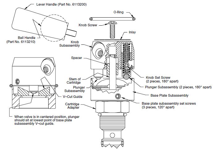
Spring-Centered Knob Kit Piece Part List:
| Handle (see Figure 1 below) qty: 1 Knob Screw (Part No. 6111021) qty: 1 Inlay (Part No. 6109610) qty: 1 Knob Subassembly (Part No. 6503420) qty: 1 Subassembly includes: Set Screws (Part No. 6111011) qty: 2 Spacer (Part No. 7010281) qty: 1 Plunger Subassembly (Part No. 6503410) qty: 1 Retainer (Part No. 7011881) qty:1 Spring (Part No. 7010416) qty: 1 Spring (Part No. 7010426) qty: 1 Knob (Part No. 7011271) qty: 1 |
Base Plate Subassembly (Part No. 6503620) qty: 1 Subassembly includes: Set Screws (Part No. 6111012) qty: 3 V-Cut Guide (Part No. 7010376) qty: 1 Stud (Part No. 6107500) qty: 1 Base Plate (7010271) qty: 1 O-Ring (Part No. 6023001) qty: 1 3/32 Hex Key Wrench, not shown (Part No. 6107490) qty:1 Tools Required: 3/32 Hex Key Wrench (included in kit) 1" Hex Torque Wrench 1/4" Flat Head Screwdriver (for adapter lock-down kit only) |
Figure 1: Exploded Assembly:

Figure 2: Centering the Valve:

Figure 3: Lock-Down Plate Kit (Optional) for use with 8TL Body Only:

Spring Centered Knob Installation Instructions:
Please read these instructions and review Fiqures 1, 2 & 3 (above) before assembling
| 1) With cartidge valve in hand, line up the alignment marks of the stem and adapter as shown in Figure 3. (This will locate valve center position which is critical to valve operation.) 2) Install cartridge valve. 3) Verify that alignment marks are aligned after installing valve. 4) If lock-down plate kit is being used, see Figure 3. A) Body or manifold must have 1/4–20 UNC threaded hole. B) Place lock-down plate over cartridge hex and position slot over body or manifold lock-down hole (1/4–20 UNC threaded hole). Install 1/4–20 UNC screw and washer; tighten to 7-8 ft-lbs. 5) Place base plate subassembly (V-cut up) over stem and adapter of cartridge (see Figure 1). Do not tighten base plate subassembly set screws at this time. 6) Place spacer onto adjusting stem positioning the outer groove of spacer downward (toward cartridge adapter) as shown in Figure 1. 7) If handle is not attached to knob, screw handle into knob. 8) Make sure knob subassembly set screws are flush with outside diameter of knob. Carefully place knob subassembly (with plungers facing downward) over stem, aligning plungers with the lowest point of the V-cut in the base plate subassembly, as shown in Figure 1. (Optional: Lightly grease V-cut Guide.) 9) Gently rotate knob subassembly and base plate subassembly together, keeping plunger aligned in lowest point of V-cut, and orienting handle to the desired position when valve is centered. It is important that stem does not rotate while rotating knob subassembly and base plate subassembly. If stem does rotate, repeat steps beginning from step 1. |
10) Once handle is in desired centered position, hold base plate subassembly down on adapter and tighten the three base plate set screws, alternating tightening sequence to center base plate on adapter as best as possible. Tighten to 1-1/2 to 2 ft-lbs. 11) After base plate is secure, screw in knob subassembly set screws until they contact the spacer. Then press down firmly on knob and tighten two knob set screws to 1-1/2 to 2 ft-lbs, alternating tightening sequence, as done in step 10. Knob may lift when released. 12) Position inlay on top of knob as desired and insert knob screw into top hole of knob. Tighten knob screw, drawing knob toward adjusting stem until knob bottoms out on stem. 13) To verify proper assembly, rotate handle both CW and CCW and make sure rotation in both directions is equal (45°). 14) Optional: Install O-ring in the gap between the knob subassembly and base plate subassembly, as shown in Figure 1. This step is recommended when operating in an environment where dust and moisture may be present. 15) If rotation is unequal in both directions or desired handle position is incorrect, remove knob screw, loosen base plate subassembly set screws, and loosen knob set screws, making sure there is no contact between knob set screws and spacer. Repeat steps 3-12. |


